
Magneto-dielectric substrate, circuit material, and assembly having the same

a technology of dielectric substrate and circuit material, applied in the direction of magnetic materials, magnetic bodies, organic/organometallic films, etc., can solve the problems of not providing the desired bandwidth or mechanical performance for a given application, unable to achieve the desired mechanical performance, and unable to meet the requirements of a given application, etc., to achieve the development of materials with sufficient flame retardancy,

Inactive Publication Date: 2016-09-22
ROGERS CORP
View PDF9 Cites 19 Cited by
  • Summary
  • Abstract
  • Description
  • Claims
  • Application Information

AI Technical Summary

Benefits of technology

The patent describes a magneto-dielectric substrate that has a magnetic constant of less than or equal to 3.5 from 500 MHz to 1 GHz and a magnetic loss of less than or equal to 0.1 or 0.8 over the same range. The substrate is made by dispersing a plurality of hexaferrite particles in a curable polymer matrix and curing it to form a layer with the desired properties. The technical effect of this invention is a material that can be used in various applications such as RF components and antennas, which has improved performance and efficiency.

Problems solved by technology

However, these materials are not entirely satisfactory, in that they may not provide the desired bandwidth or have the desired mechanical performance for a given application.
Developing materials with sufficient flame retardancy has been particularly difficult because the particulate metallic fillers used to impart the desired magneto-dielectric properties are combustible.
Such fillers are also not stable under high humidity conditions, even when surrounded by the polymeric matrix.

Method used


Image

  • Magneto-dielectric substrate, circuit material, and assembly having the same
  • Magneto-dielectric substrate, circuit material, and assembly having the same
  • Magneto-dielectric substrate, circuit material, and assembly having the same

Examples


examples 1 to 5

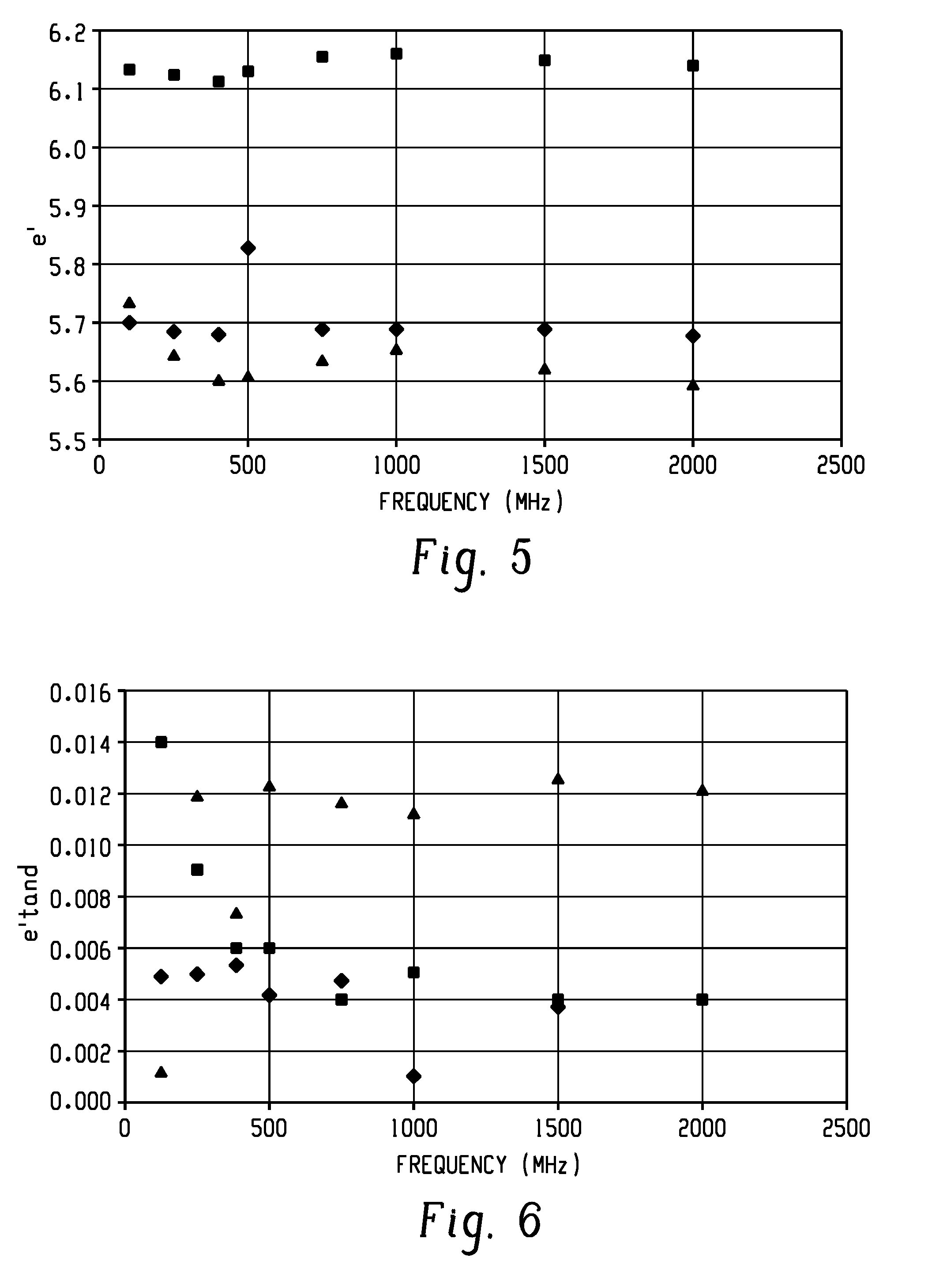
[0088]Layers comprising a magnetic particle and a polymer matrix were tested over a range of frequencies as described below.

[0089]The layer of Example 1 comprises VH magnetic particles in a thermosetting polybutadiene / polyisoprene material as described above (RO4000 with no dielectric filler or glass cloth from Rogers Corporation) is denoted in FIGS. 5-8 by the diamonds. The VH magnetic particles are barium cobalt Z Type hexaferrite (Co2Z Ferrite) that are doped with either iridium or molybdenum to improve the resistivity of the particles.

[0090]The layer of Example 2 comprises TT2 500 magnetic particles commercially available from Transtech in a thermosetting polybutadiene / polyisoprene material as described above (RO4000 with no dielectric filler or glass cloth from Rogers Corporation) is denoted in FIGS. 5-8 by the squares.

[0091]The layer of Example 3 comprises SMMDP400 magnetic Co—Ba-hexaferrite particles that are iron coated with a silicon layer, for example, to prevent rusting, ...

embodiment 1

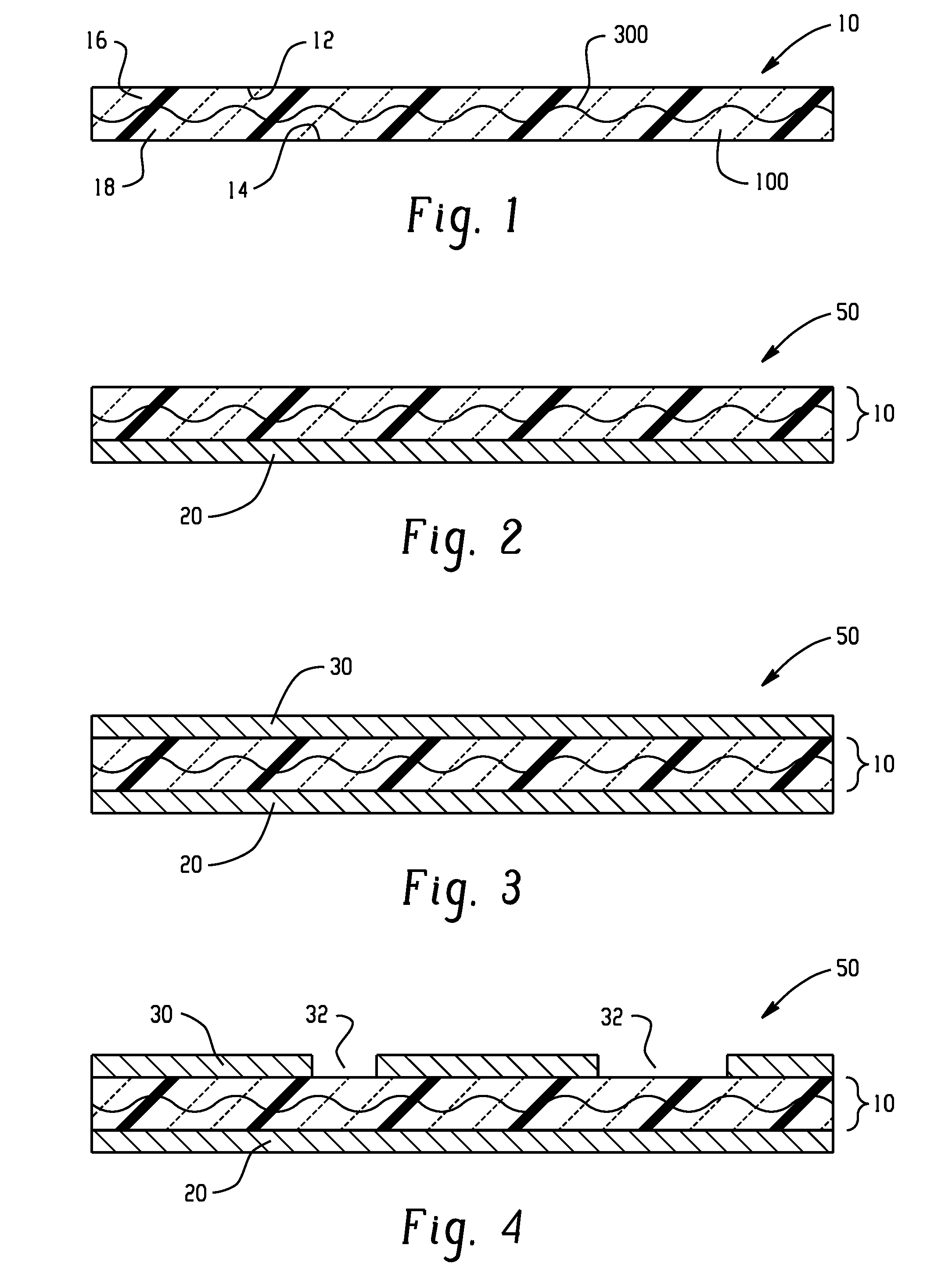
[0099]A magneto-dielectric substrate, comprising: a dielectric polymer matrix; and a plurality of hexaferrite particles dispersed in the dielectric polymer matrix in amount and of a type effective to provide the magneto-dielectric substrate with a magnetic constant of less than or equal to 3.5, or less than or equal to 2.5 from 500 MHz to 1 GHz, or 1 to 2 from 500 MHz to 1 GHz, and a magnetic loss of less than or equal to 0.1 from 500 MHz to 1 GHz, or 0.001 to 0.07 over 500 MHz to 1 GHz.

embodiment 2

[0100]The magneto-dielectric substrate of embodiment 1, wherein the magneto-dielectric substrate further has at least one of a dielectric constant of greater than or equal to 1.5, or 1.5 to 8 from 500 MHz to 1 GHz; a dielectric loss of less than 0.01 or less than 0.005 over 500 MHz to 1 GHz; a UL94 V1 rating measured at a thickness of 1.6 mm; and a peel strength to copper of 3 to 7 pli measured in accordance with IPC test method 650, 2.4.9.


PUM

PropertyMeasurementUnit
wt %aaaaaaaaaa
sizeaaaaaaaaaa
sizeaaaaaaaaaa

Abstract

In an embodiment, a magneto-dielectric substrate comprises a dielectric polymer matrix; and a plurality of hexaferrite particles dispersed in the dielectric polymer matrix in amount and of a type effective to provide the magneto-dielectric substrate with a magnetic constant of less than or equal to 3.5 from 500 MHz to 1 GHz, or 3 to 8 from 500 MHz to 1 GHz, and a magnetic loss of less than or equal to 0.1 from 0 to 1 GHz, or 0.001 to 0.07 over 0 to 1 GHz.

Description

CROSS REFERENCE TO RELATED APPLICATIONS[0001]This application claims the benefit of U.S. Provisional Application No. 62 / 135,280, filed Mar. 19, 2015, which is incorporated by reference in its entirety herein.BACKGROUND[0002]The present disclosure relates generally to a magneto-dielectric substrate useful in applications such as metal clad circuit materials for circuits, antennas, and the like.[0003]Newer designs and manufacturing techniques have driven electronic components to increasingly smaller dimensions, for example, components such as inductors on electronic integrated circuit chips, electronic circuits, electronic packages, modules and housings, UHF, VHF, and microwave antennas. One approach to reducing electronic component size has been the use of magneto-dielectric materials as substrates. In particular, ferrites, ferroelectrics, and multiferroics have been widely studied as functional materials with enhanced microwave properties. However, these materials are not entirely s...

Claims


Application Information

Patent Timeline
Patent Type & Authority Applications(United States)
IPC IPC(8): H01F1/03
CPCH01F1/0315H01F1/348H01F17/0006H05K1/0373H05K2201/086H01F1/37H01F10/005
Inventor SETHUMADHAVAN, MURALIHORN, III, ALLEN F.SPRENTALL, KARL EDWARDWHITE, MICHAEL
Owner ROGERS CORP
Learn More