Electric wire and coil
a technology which is applied in the direction of insulated conductors, cables, conductors, etc., can solve the problems of difficult design of electric wire and coil, and achieve the effect of reducing ac resistance equal or less, easy design, and easy design of electric wir
- Summary
- Abstract
- Description
- Claims
- Application Information
AI Technical Summary
Benefits of technology
Problems solved by technology
Method used
Image
Examples
first embodiment
Electric Wire and Coil
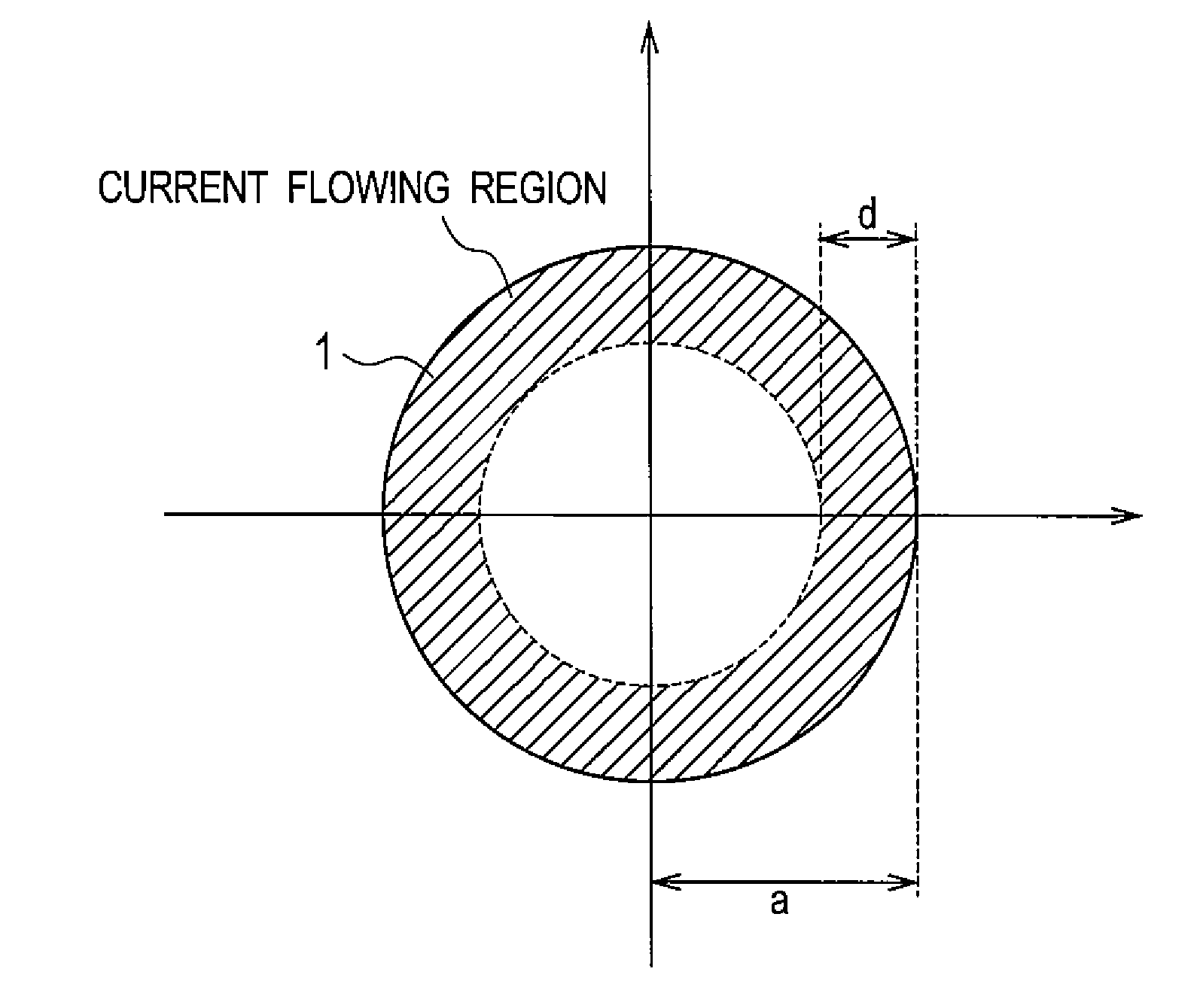
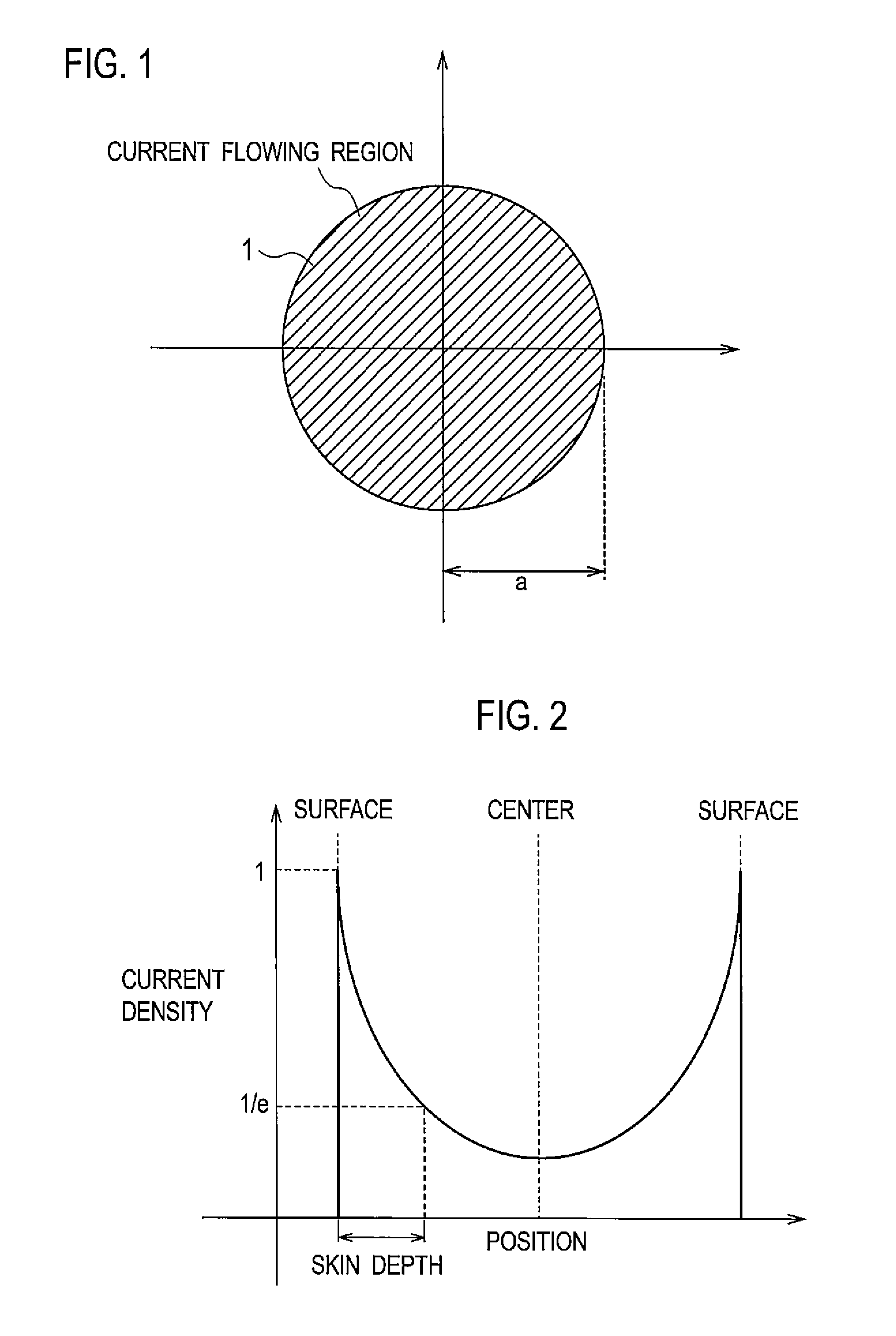
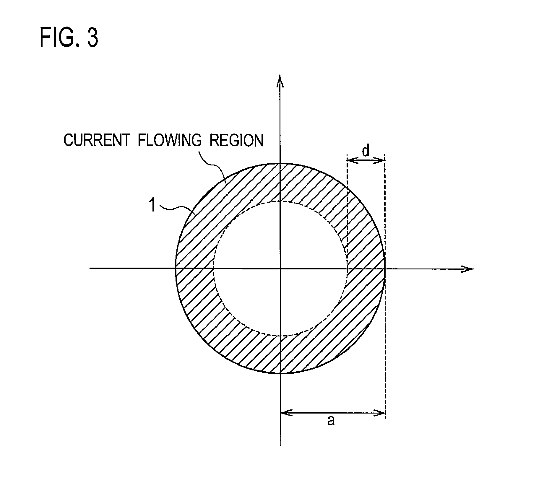
[0032]An electric wire 1 according to a first embodiment of the present invention, as shown in FIG. 1, is made of a wire material having lower conductivity than copper where a radius a of the electric wire 1 is smaller than a skin depth thereof, and an AC resistance value of the electric wire 1 at a frequency used in the electric wire 1 is provided in excess of a sum of a direct current (DC) resistance value of the electric wire 1 and a DC resistance value of the copper wire having the same shape and the same outer diameter as the electric wire 1.
[0033]As shown in FIG. 2, when an AC current is flowing through a conductor, the current density is largest at a conductor surface, and the current density exponentially decreases in a direction from the conductor surface to the conductor center. This is called the skin effect. In this case, the depth of a current density value obtained by multiplying the current density at the conductor surface by “1 / e” is defined as ...
second embodiment
Electric Wire and Coil
[0065]An electric wire 1 according to a second embodiment of the present invention, as shown in FIG. 8, is a wire material having a double layered structure in which an inner layer (first layer) 2 and an outer layer (second layer) 3 around the periphery of the inner layer 2 are formed, and the inner layer 2 is made of a substance having lower conductivity than copper and the outer layer 3 is made of copper. Then, the electric wire 1 according to the second embodiment of the present invention has a radius a of the electric wire 1 which is smaller than the skin depth, and an AC resistance of the electric wire 1 at a frequency used in the electric wire 1 is provided in excess of a sum of a value obtained by multiplying a DC resistance value of the electric wire 1 by a ratio of a cross-sectional area of the inner layer 2 and a cross-sectional area of the entire electric wire 1, and a DC resistance value of the copper wire having the same shape and the same outer di...
example
[0080]The results of the AC resistances of the coils wound 42 turns to the bobbin having an inner diameter of 20.0 mm by twisted four enameled wires made of copper or CCA each having an outer diameter of 0.6 mm and a finished diameter of 0.63 mm, measured with LCR meter is shown in FIGS. 9 and 10. In FIG. 9, the calculated resistance values of the copper wire coil (hereinafter, also referred to as “Cu coil”) and the CCA wire coil (hereinafter, also referred to as “CCA coil”) by the above equation (5) are also shown. Here, calculation has been done with the conductivity of copper as 5.80×10⁴ Ω−1mm−1 and the conductivity of aluminum as 3.70×10⁴ Ω−1mm−1. In addition, the shape factor α has been obtained as 2.4 mm−1 by comparison of the calculated value from the equation (5) and the measured value.
[0081]The DC resistance of the Cu coil is 47.4 mΩ, the DC resistance of CCA coil is 69.9 mΩ, and thus, the DC resistance of the Cu coil is lower than the DC resistance of the CCA coil. However...
PUM
| Property | Measurement | Unit |
|---|---|---|
| frequency | aaaaa | aaaaa |
| frequency | aaaaa | aaaaa |
| diameter | aaaaa | aaaaa |
Abstract
Description
Claims
Application Information
 - R&D
- Intellectual Property
- Life Sciences
- Materials
- Tech Scout
- Unparalleled Data Quality
- Higher Quality Content
- 60% Fewer Hallucinations
Browse by: Latest US Patents, China's latest patents, Technical Efficacy Thesaurus, Application Domain, Technology Topic, Popular Technical Reports.
© 2025 PatSnap. All rights reserved.Legal|Privacy policy|Modern Slavery Act Transparency Statement|Sitemap|About US| Contact US: help@patsnap.com


