
Fused filament fabrication using liquid cooling

a technology of liquid cooling and fused filament, which is applied in the direction of additive manufacturing apparatus, applying layer means, etc., can solve the problems of frequent clogging of 3d printers using fff processing, excessive plug state, and excessive plug state, so as to facilitate the use of high-temperature, high-viscosity materials, and prevent or substantially reduce the incidence of clogging

Inactive Publication Date: 2016-09-22
AREVO INC
View PDF4 Cites 44 Cited by
  • Summary
  • Abstract
  • Description
  • Claims
  • Application Information

AI Technical Summary

Benefits of technology

The present innovation prevents clogging of high-temperature, high-viscosity materials during 3D printing via FFF processing. This allows for the use of such materials without the limitations of the prior art. By ensuring a small plug state, the system is less prone to clogging. This is achieved by controlling the temperature and viscosity of the material being printed, specifically by ensuring a relatively small temperature and viscosity for semi-crystalline polymers near their melting point.

Problems solved by technology

Prior art 3D printers are suitable for printing parts made some polymers, such as acrylonitrile butadiene styrene (ABS), polylactic acid (PLA), and polyetherimide (PEI), but not for printing parts made from other polymers, particularly high-temperature polymers such as polyether ether ketone (PEEK), polyamide-imine (PAI) and self-reinforced polyphenylene (SRP).
It is known in the art that when trying to print parts made from the aforementioned high-temperature polymers, 3D printers using FFF processing frequently clog.
If the time in the plug state is too long, the pressure of the system surpasses the maximum torque of the motor and the filament clogs.
The same situation results if the plug state is physically too long.
However, at the higher operating temperatures required for high-temperature semi-crystalline polymers, such as PEEK, PAI, and SRP, a substantial amount of heat is being conducted to the cooling black.
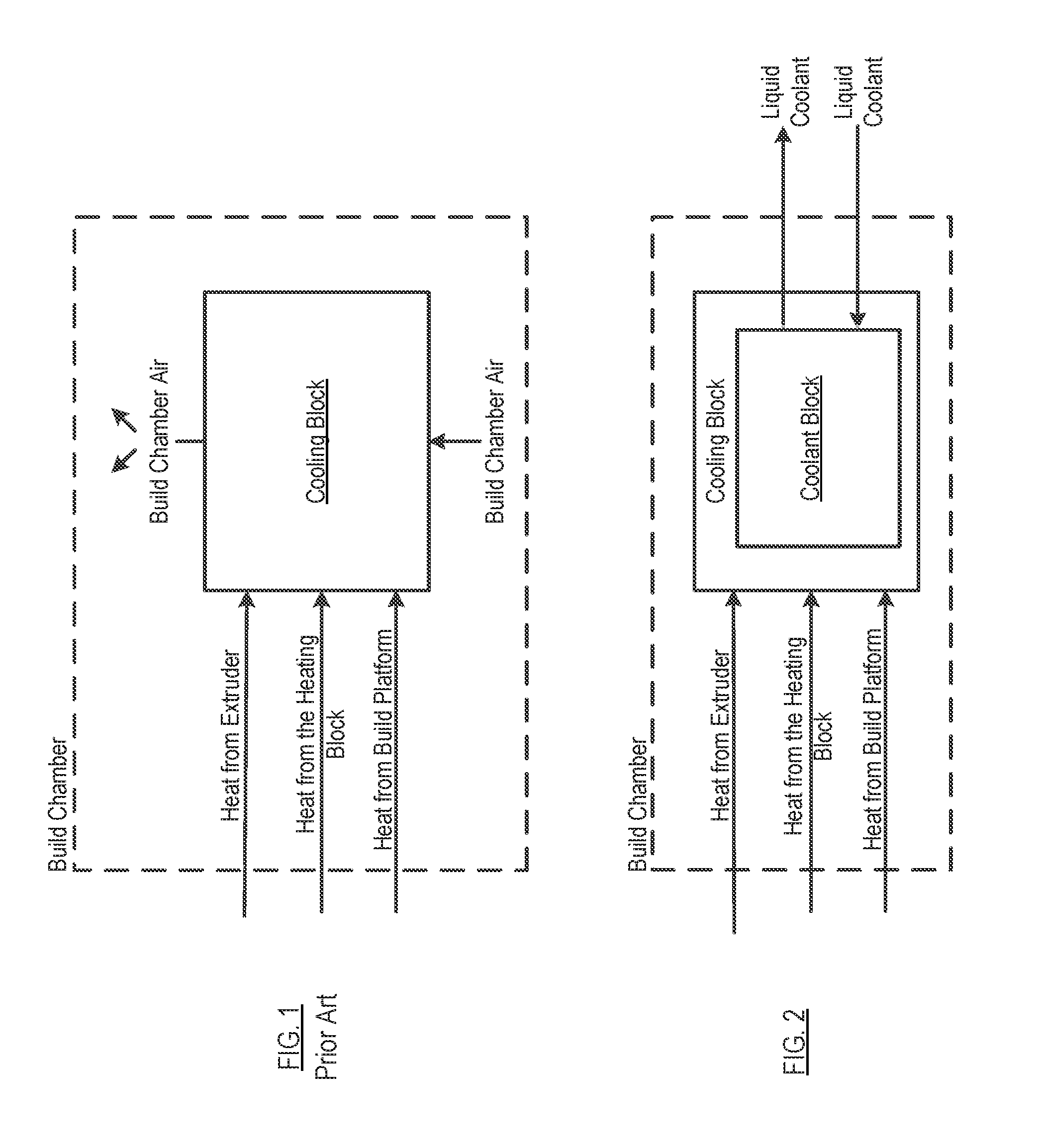
A fan, as used in the prior art, which is simply circulating air from within the build chamber over the cooling block, is insufficient for providing the requisite cooling.
And that is the reason for the clogging experienced in the prior art with such high temperature semi-crystalline polymers.
The air being blown over the cooling block provides localized cooling, but it cannot cool the cooling block to less than the temperature of the build chamber.

Method used


Image

  • Fused filament fabrication using liquid cooling
  • Fused filament fabrication using liquid cooling
  • Fused filament fabrication using liquid cooling

Examples


Embodiment Construction

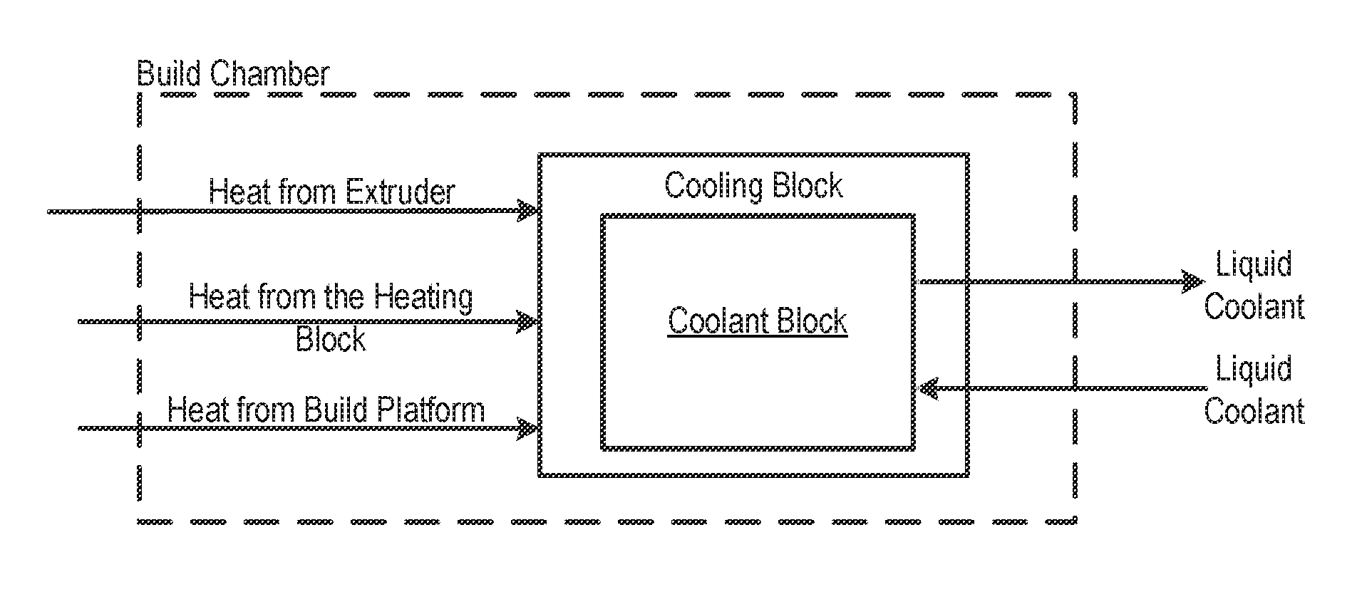
[0029]As described in the background, in prior-art FFF systems, a fan is used to remove heat from the cooling block thereby preventing clogging and reducing pressure in the system. For most FFF systems, the cooling block is cooled by a fan that blows air (sourced from the build chamber) over the cooling block. As a consequence, the cooling block temperature is, at best, maintained at the build chamber temperature.

[0030]In accordance with the present teachings, a modified FFF system and method are disclosed wherein liquid cooling is used to reduce the temperature of the cooling block below the build chamber temperature.

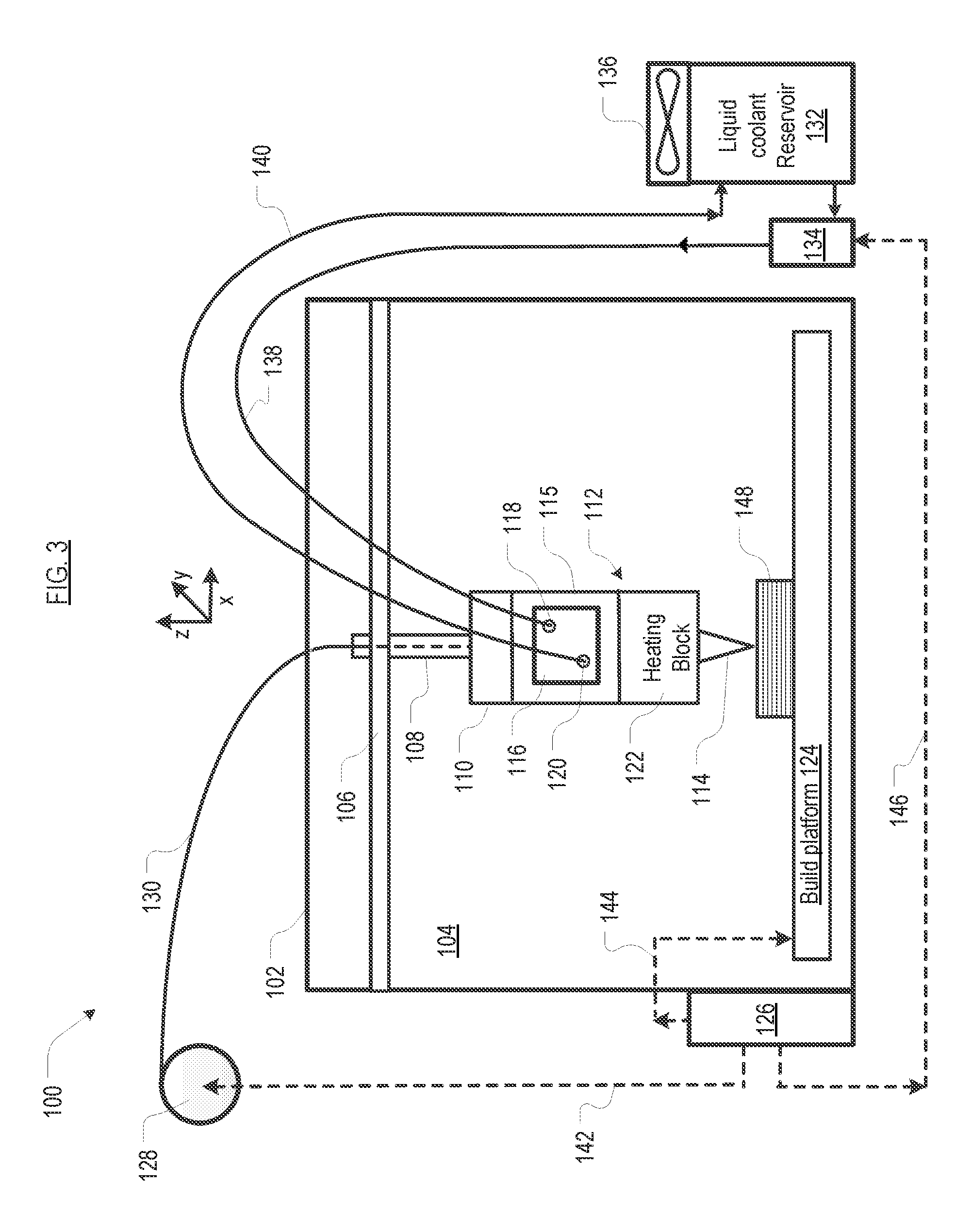
[0031]FIG. 3 depicts system 100 for 3D printing, which utilizes a modified FFF-based process. System 100 includes housing 102, build chamber 104, gantry 106, fixture 110, extruder head 112, cooling block 115, heating block 122, build platform 124, controller 126, and a thermal management system, interrelated as shown. As discussed further below, a distinguishing charac...


PUM

PropertyMeasurementUnit
Temperatureaaaaaaaaaa
Viscosityaaaaaaaaaa
Dimensionaaaaaaaaaa

Abstract

A FFF-based 3D printer includes a thermal management system that incorporates liquid cooling for the cooling block. In the illustrative embodiment, the thermal management system includes a coolant block that couples to the surface of the existing cooling block, a liquid-coolant reservoir, a fan for cooling the reservoir, a pump for pumping the coolant, and conduits for conducting the coolant to and from the coolant block. Embodiments of the invention provide a way to prevent or substantially reduce the incidence of clogging as otherwise occurs when attempting to print high-temperature, high-viscosity materials using FFF-based 3d printers.

Description

STATEMENT OF RELATED CASES[0001]This case claims priority of U.S. Pat. App. Ser. No. 62 / 133,666 filed Mar. 16, 2015, which is incorporated by reference herein.FIELD OF THE INVENTION[0002]The present invention relates generally to fused filament fabrication.BACKGROUND OF THE INVENTION[0003]The additive manufacturing process is widely known as “3d printing.” Numerous 3d-printing methodologies have been described in prior art, the most common being solid-laser sintering (SLS), stereolithography (SLA), and extrusion-based 3d printing or fused filament fabrication (FFF).[0004]All of these methods involve depositing a thin layer of thermoplastic or thermoset materials. In FFF, thin strands of material (referred to herein as “extrudate” once it leaves the deposition nozzle) are deposited onto a build surface. As the filament moves through the FFF system, it undergoes mechanical, chemical, and thermal changes. Deposition proceeds in a controlled pattern on the build surface to construct a 3...

Claims


Application Information

Patent Timeline
IPC IPC(8): B29C67/00
CPCB29C67/0085B29C67/0055B29K2071/00B29K2079/085B33Y40/00B33Y10/00B33Y30/00B33Y70/00B29K2065/00B29C2035/1616B29C64/209
Inventor BHEDA, HEMANTREESE, RILEY
Owner AREVO INC
Learn More