
Devices for separation of biological materials

a biological material and device technology, applied in the direction of electrostatic separators, solid separation, chemistry apparatus and processes, etc., can solve the problems of large sample volume and bulky current techniques

Active Publication Date: 2016-09-22
BIOLOGICAL DYNAMICS INC
View PDF1 Cites 7 Cited by
  • Summary
  • Abstract
  • Description
  • Claims
  • Application Information

AI Technical Summary

Benefits of technology

This method enables rapid isolation of nanoscale analytes with high purity and concentration, reducing the need for further processing, and allows for direct analysis and diagnostic use, while also being suitable for multiplexed and high-throughput operations.

Problems solved by technology

Current techniques are typically bulky, requiring large volumes of sample for operation.

Method used


Image

  • Devices for separation of biological materials
  • Devices for separation of biological materials
  • Devices for separation of biological materials

Examples


example 1

[0200]A two-chamber fluidics cartridge containing a hydrogel coated microlectrode array was loaded into an ATS system. The microelectrode array comprised electrodes in a hollow ring shape, as depicted in FIG. 5. In one chamber, a standard solution with conductivity of 0.8 S / m and spiked DNA (genomic purchased from Promega or Lambda purchased from BioLabs) at 25 pg / μL was loaded for a total volume of 530 μL. In the other chamber, an unknown sample in a bodily fluid (blood, serum, plasma, sputum, etc. . . . ) was loaded to a total of 530 μL. The DNA was stained at a ratio of 1:5000× using YOYO®-1 green fluorescent dye purchased from Life Technologies. Both liquids were run on the ATS system at 10 Volts peak-to-peak and 15 kHz for 10 minutes while flowing at a variable flow rate (5 to 250 μL / min) (FIGS. 6 and 7). The arrays were then washed with an isotonic buffer (water+osmolites) for another 10 minutes at a variable flow rate in order to remove all matter that was not captured on the...

example 2

[0201]Various electrode designs were tested according to the methods described in Example 1. Generally, electrode geometry that increased FDEP while attenuating FFLOW enabled the stronger capture of nanoscale analytes. Below is a description of ACE performance difference between electrode designs.

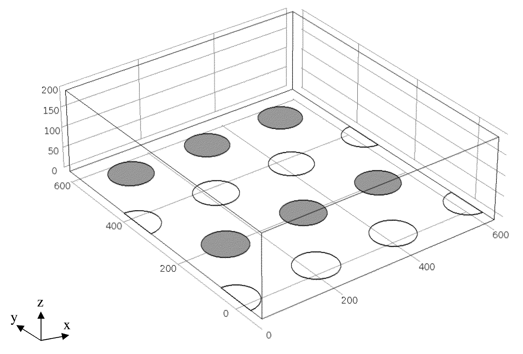
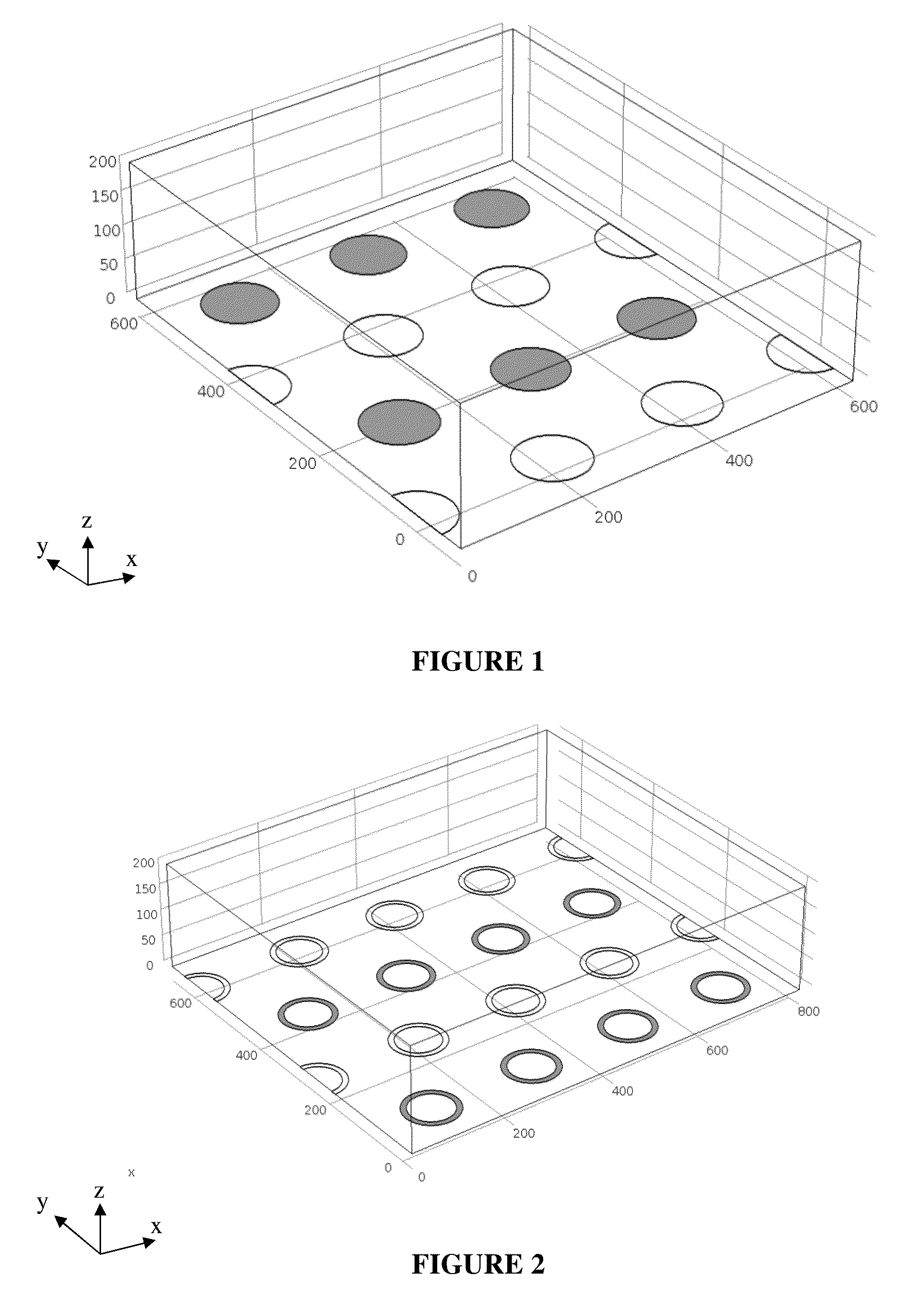
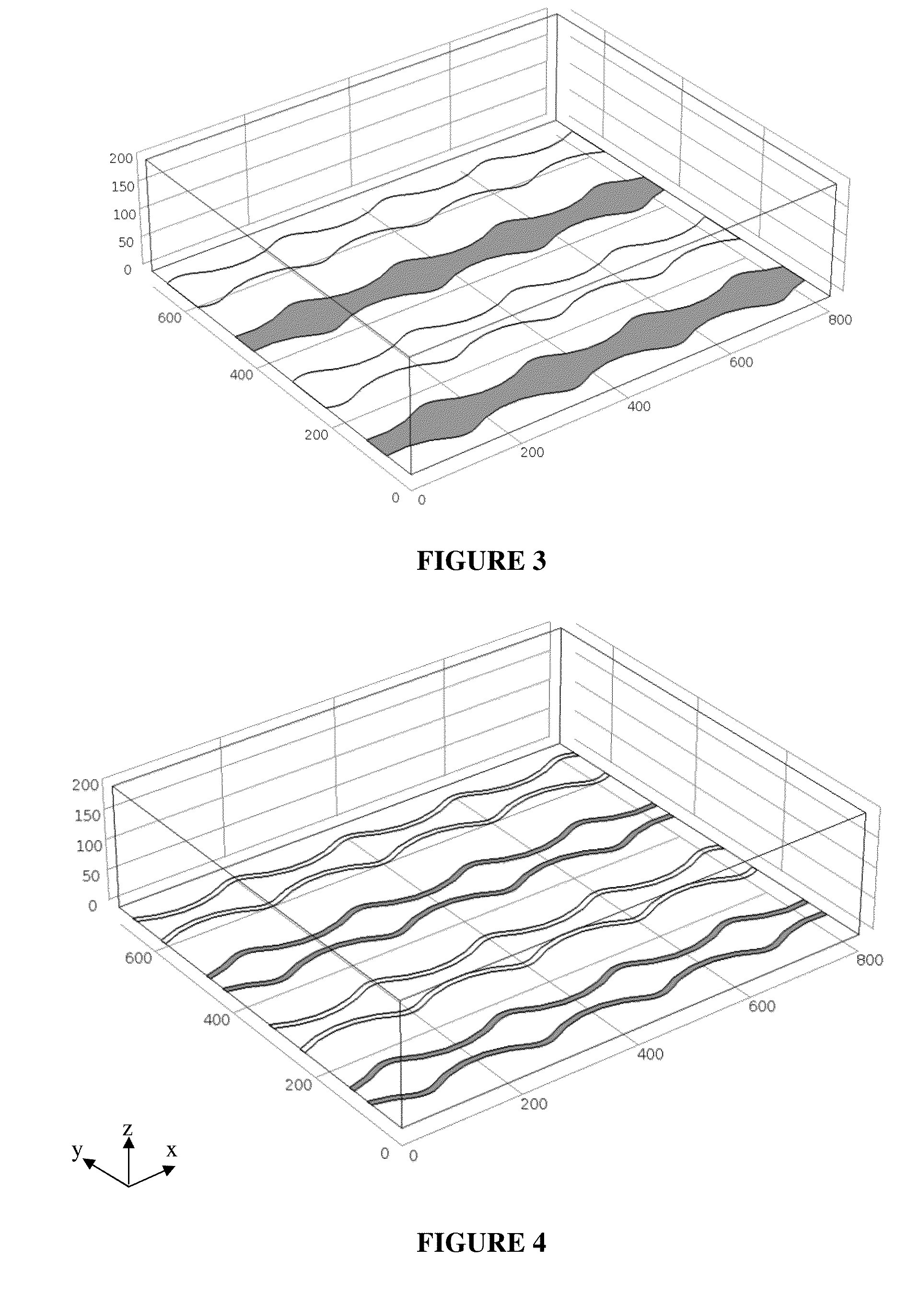
TABLE 2Description of ACE performance differencesbetween electrode designs.ElectrodeDesignRemarksHollow DiskStandard electrode geometry as shown in FIGS. 1, 6, 7, 8Hollow RingIncreased surface area for nanoscale analyte capture.Modification of flow pattern. Shown in FIG. 2.Wavy LineProvides larger surface area for nanoscale analyte capture.Generates uni-axial flow. Shown in FIGS. 3 & 4.Hollow ringReduces the ACET and ACEO. Shown in FIG. 5.withextrudedcenterBlockedReduces the ACET and ACEO. Not shown.ElectrodeFloatingReduces ACET and ACEO, collectively FFLOW, whileElectrodeincreasing FDEP. Shown in FIG. 12.


PUM


Abstract

The present invention includes methods, devices and systems for isolating nanoparticulates, including nucleic acids, from biological samples. In various aspects, the methods, devices and systems may allow for a rapid procedure that requires a minimal amount of material and / or results in high purity isolation of biological components from complex fluids such as blood or environmental samples.

Description

CROSS-REFERENCE[0001]This application is a continuation of U.S. patent application Ser. No. 14 / 680,819, filed Apr. 7, 2015; which claims priority to U.S. Provisional Application No. 61 / 977,249, filed Apr. 9, 2014, and U.S. Provisional Application No. 61 / 977,006, filed Apr. 8, 2014, all of which are herein incorporated by reference in their entirety.BACKGROUND OF THE INVENTION[0002]Separation of nanoscale analytes from other material present in biological samples is an important step in the purification of biological analyte material, including nucleic acids, for later diagnostic or biological characterization. Current techniques are typically bulky, requiring large volumes of sample for operation. There continues to be a need for a robust platform capable of isolating nanoscale analytes from complex biological samples using minimal sample volume without requiring additional purification steps.SUMMARY OF THE INVENTION[0003]In some instances, the present invention fulfills a need for ...

Claims


Application Information

Patent Timeline
Patent Type & Authority Applications(United States)
IPC IPC(8): B03C5/00B03C5/02
CPCB03C5/005B03C2201/26B03C5/026
Inventor CHARLOT, DAVIDHINESTROSA SALAZAR, JUAN PABLODOBROVOLSKAYA, IRINA V.YANG, KAISWANSON, PAULKRISHNAN, RAJARAM
Owner BIOLOGICAL DYNAMICS INC
Learn More