
Heat dissipation module

a technology of heat dissipation module and electronic device, which is applied in the direction of lighting, heating apparatus, instruments, etc., can solve the problems of consuming a large amount of power, affecting the operation effectiveness of electronic devices, and requiring a large space, and achieve good heat dissipation

Inactive Publication Date: 2016-09-08
ACER INC
View PDF2 Cites 11 Cited by
  • Summary
  • Abstract
  • Description
  • Claims
  • Application Information

AI Technical Summary

Benefits of technology

The invention provides a heat dissipation module that can efficiently spread heat. The module has an evaporator with a slope and a heat-isolating wall, which separates a heating region and a cooling region. Copper tubes connected to the evaporator create a loop, allowing a heat-transmitting medium to flow inside the loop. The heat from the electronic element is transferred to the medium through the heating region, and the medium flows out of the evaporator and copper tube in the same direction, increasing the flow rate and heat dissipation. Overall, this heat dissipation module has excellent heat dissipation performance.

Problems solved by technology

Part of the electronic elements carried inside these electronic devices will typically generate heat during the process of operation and affect the operation effectiveness of the electronic device.
In the above heat dissipation module, the heat dissipation fan may dissipate the heat to the outside effectively, however it consumes a large amount of power, is heavier, requires a larger space and is not advantageous to be used on an electronic device that pursues a light and thin design, and furthermore is susceptible to noise which affects the additional communication functions of the electronic device.
In addition, in order for the heat dissipation fan to perform heat dissipation through convection, an opening is required to be disposed on the outer shell of the electronic device, which also lowers the structural strength of the electronic device.
However, it is difficult to further dissipate the heat to the outside through other components, limiting its heat dissipation effect.
Furthermore, a heat dissipation pipe may transmit the heat of the electronic element onto another plate, however it lacks in convection and therefore the cooling effect is limited.
However, the heat-transmitting medium only flows in the loop through the phase change of it self, in which the flow effect is poor, thus limiting the heat dissipation effect thereof.

Method used


Image

  • Heat dissipation module
  • Heat dissipation module
  • Heat dissipation module

Examples


Embodiment Construction

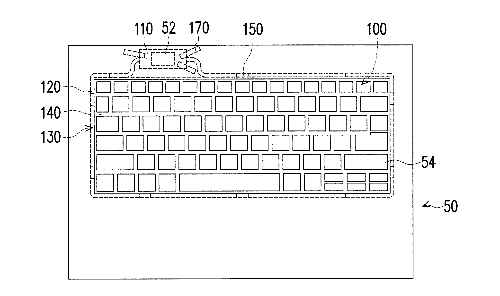
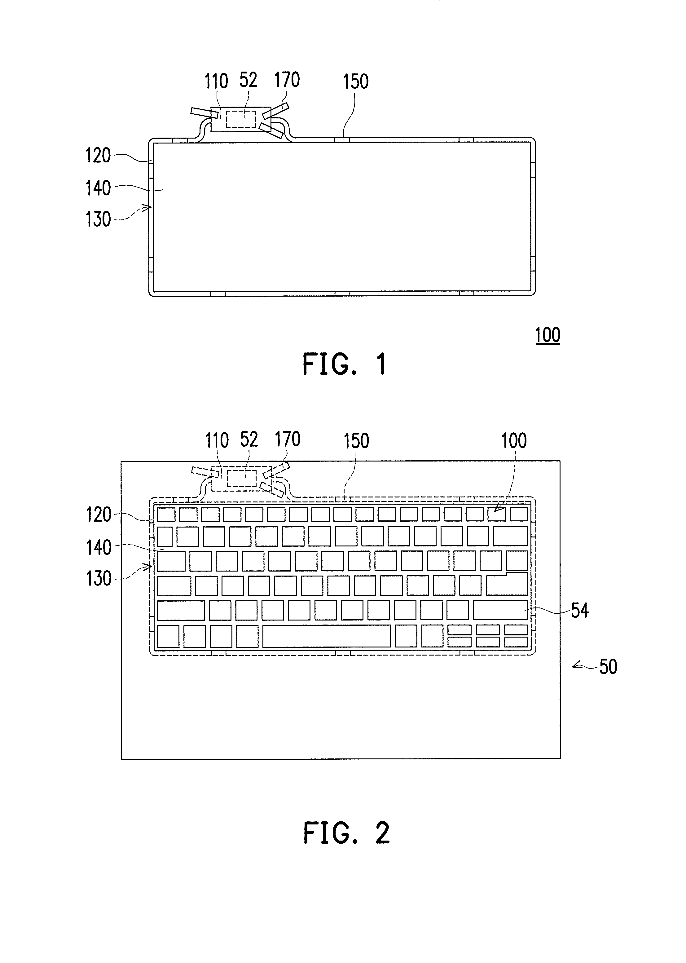
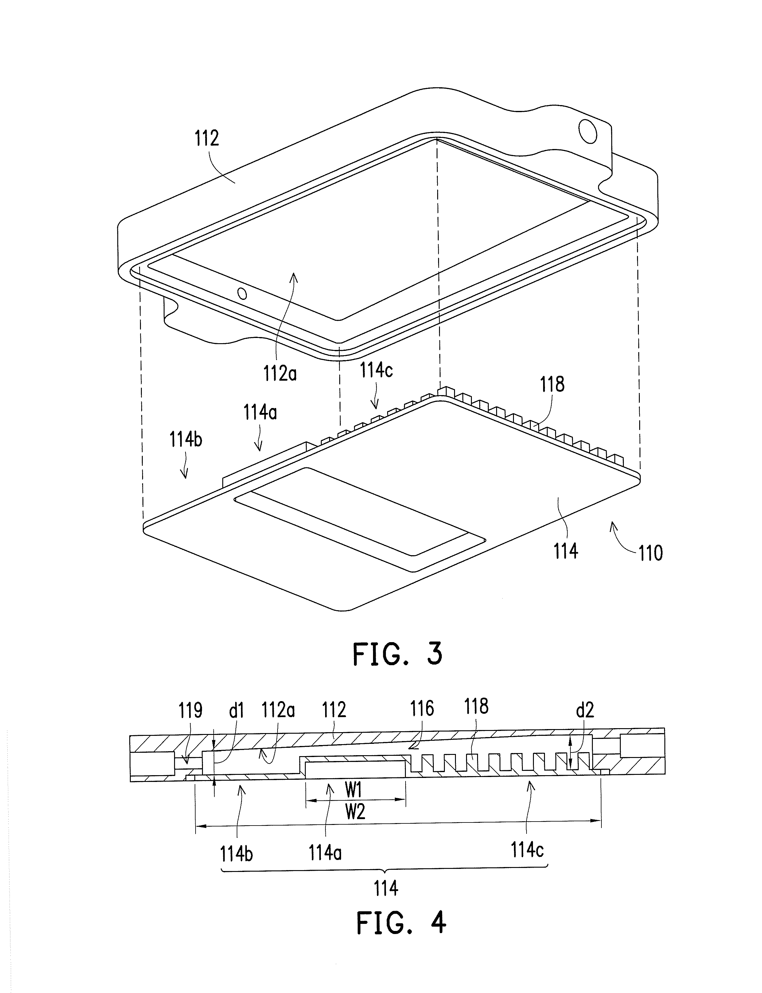
[0016]FIG. 1 is a top schematic view of a heat dissipation module according to an embodiment of the invention.FIG. 2 is a top schematic view of the heat dissipation module of FIG. 1 used in an electronic device. Referring to FIG. 1 and FIG. 2, in the present embodiment, a heat dissipation module 100 is adapted for an electronic device 50. The electronic device may be an electronic device having a single body, or also may be an electronic device having two bodies, for example, a notebook, and only one body is shown in FIG. 1; however the type of electronic device should not be construed as a limitation to the invention. An electronic element 52 such as a central processing unit (CPU) or other suitable electronic element is disposed inside the electronic device 50 to execute related operations. The electronic element 52 generates heat during the process of operation. In this way, the heat dissipation module 100 of the present embodiment is adapted to be disposed in the electronic devi...


PUM


Abstract

A heat dissipation module including an evaporator, a copper tube communicated with the evaporator to construct a loop, and a heat-transmitting medium flowing in the loop is provided. The evaporator includes an upper cover and a lower cover connected with each other and constructing a cavity. The lower cover has a heat-isolating wall protruded toward the cavity, so as to separate a heat-isolating region and a heating region at the lower cover. The upper cover has a slope inclining toward the cavity. A heat of an electronic element is transmitted to the heat-transmitting medium through the heating region, so that the heat-transmitting medium flows out of the evaporator towards a single direction along the slope after absorbing the heat, flows in the copper tube to transmit the heat outward through the copper tube, and then flows back to the evaporator through the copper tube after dissipating the heat.

Description

CROSS-REFERENCE TO RELATED APPLICATION[0001]This application claims the priority benefit of Taiwan application serial no. 104107288, filed on Mar. 6, 2015. The entirety of the above-mentioned patent application is hereby incorporated by reference herein and made a part of this specification.BACKGROUND OF THE INVENTION[0002]1. Field of the Invention[0003]The invention relates to a heat dissipation module, and relates particularly to a heat dissipation module of an electronic device.[0004]2. Description of Related Art[0005]In recent years, along with developments of the industrial technology industry, electronic devices, for example, products such as notebooks, personal digital assistants (PDA) and smart phones have become a part of our daily lives. Part of the electronic elements carried inside these electronic devices will typically generate heat during the process of operation and affect the operation effectiveness of the electronic device. Therefore, generally a heat dissipation m...

Claims


Application Information

Patent Timeline
Patent Type & Authority Applications(United States)
IPC IPC(8): F28D15/02G06F1/20G06F1/16F28F13/00
CPCF28D15/02F28F13/00F28D2015/0216G06F1/1662G06F1/20F28D15/0266F28F3/12F28F13/08F28F13/14F28F2013/006G06F1/203
Inventor WANG, YUNG-CHIHHSIEH, CHENG-WENHUANG, TING-CHIANGLIAO, WEN-NENG
Owner ACER INC
Learn More