Eureka AIR delivers breakthrough ideas for toughest innovation challenges, trusted by R&D personnel around the world.

Device and method for reliably starting orc systems

a technology of orc system and device, applied in mechanical equipment, machines/engines, steam engine plants, etc., can solve problems such as cavitation, partial or complete failure of pump delivery, and damage to pumps

Active Publication Date: 2016-09-01
ORCAN ENERGY AG
View PDF5 Cites 4 Cited by
  • Summary
  • Abstract
  • Description
  • Claims
  • Application Information

AI Technical Summary

Benefits of technology

The invention allows for a pump to be placed at a lower level than an evaporator, which increases the overall height of the system. Additionally, the condensation temperature can be adjusted by reducing the speed of a condenser fan or cooling water mass flow, or by increasing the temperature of the cooling water mass flow or air mass flow. Other measures such as closing louvers or shutters can also lead to an increase in the condensation temperature. These technical effects improve the efficiency and performance of the cooling system.

Problems solved by technology

This phenomenon may lead to pump damage and to a partial or complete failure of pump delivery.
Especially for circulation systems, like an ORC, cavitation is a challenge.
When an ORC system is shut down, e.g. due to failure / deactivation of the heat source or due to an emergency shutdown of the system, this may lead to an uncontrolled distribution of working medium in the system (e.g. in the expansion machine, horizontal tubes or fluid pouches); in this case, the working medium will not flow to the feed tank.
This may have the effect that the amount of working medium available for the feed pump does not suffice for the whole startup process.
The disadvantageous distribution of working medium and the resultant difficult or even impossible startup is a well known problem for which various solutions are suggested in the prior art.
In the case of the compact structural design of ORC systems this is, however, difficult to realize or cannot be realized at all, especially if a maximum overall height has to be observed.
Even if the evaporator were accommodated at the highest point, which would cause the working medium to collect automatically in the condenser / feed tank, the problem of system conditions with an insufficient applied head height NPSHa, as described hereinbefore, would not be solved.
However, the two above-mentioned prior art disclosures also fail to solve a further problem: when the ORC system is being started, a situation may arise in which the feed pump and possibly also the feed line thereof may have a temperature that is higher than that of the working medium sucked in from the condenser or the working medium just condensing in the condenser.
This prevents starting of the system and may cause damage to the pump.
Even after temperature compensation between the feed pump, the feed line and the condenser, the then applied head height NPSHa may, in particular in systems having a compact structural design without large differences in height and thus without much geodetic head height, be smaller than the required head height NPSHr, and this, in turn, will lead to cavitation.
In an ORC system, a maldistribution of liquid working medium may occur in the standstill condition or as a result of a poorly controlled shutdown of the system, whereby starting of the system is prevented because the amount of medium upstream of the feed pump is insufficient.
In addition, a disadvantageous temperature distribution may occur in the working medium circuit, the working medium in the area upstream of the feed pump may e.g. have a higher temperature than at the coldest point in the system.
Due to the small head height applied to the pump in this condition, cavitation of the pump may occur.
This prevents a reliable start of the system.
For example, there may be an increase in the viscosity of the working medium or of some other medium, such as a lubricant, existing in the circuit, whereby conveyance of the medium through the feed pump may be impaired.

Method used


Image

  • Device and method for reliably starting orc systems
  • Device and method for reliably starting orc systems
  • Device and method for reliably starting orc systems

Examples


embodiments

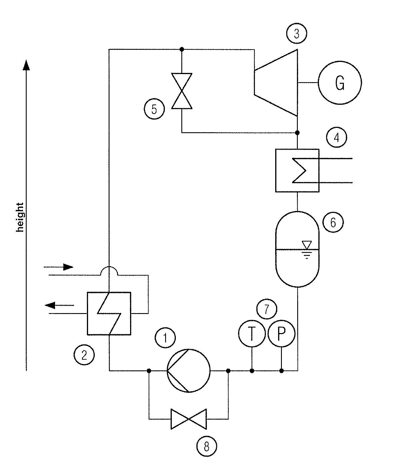
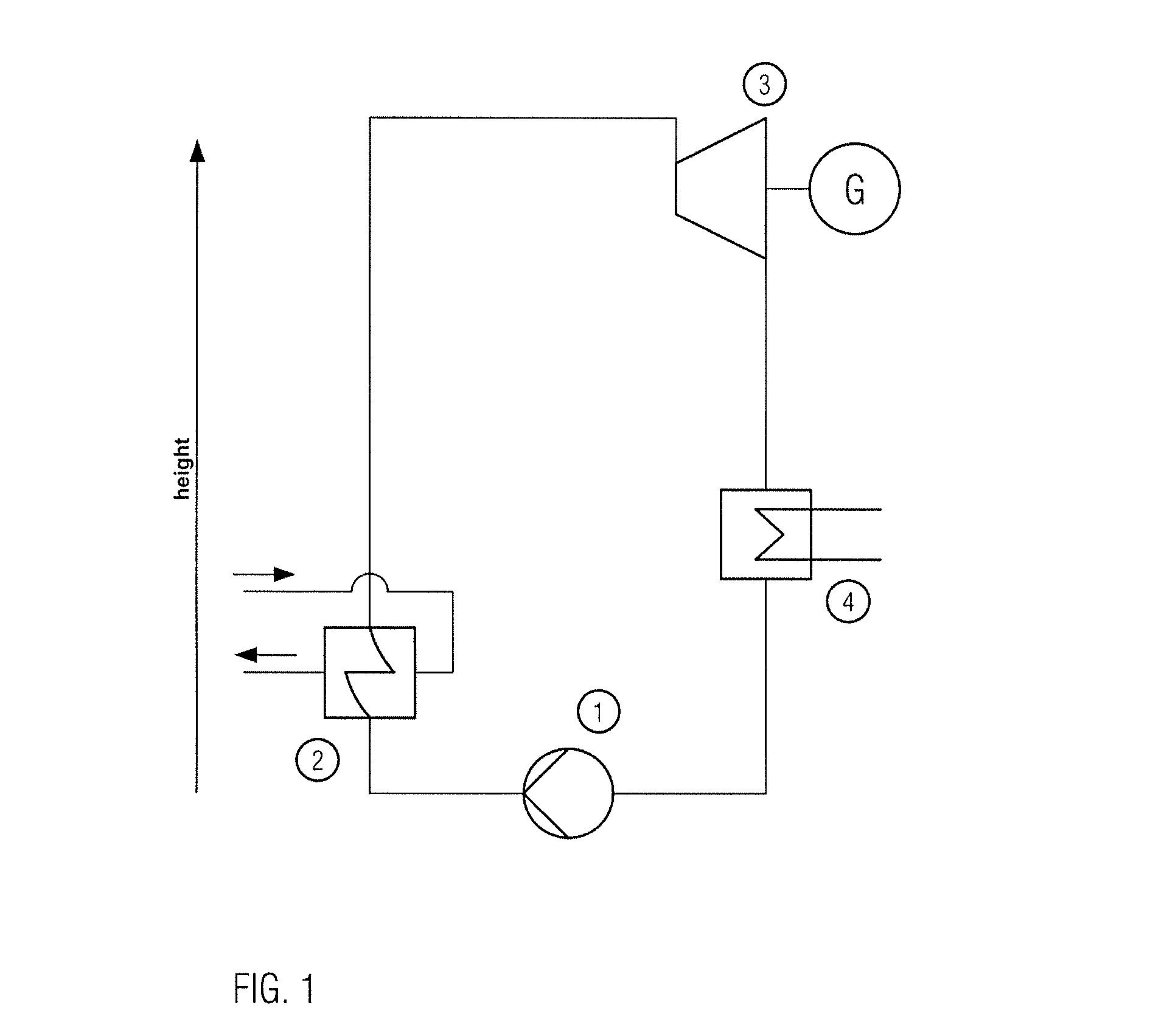
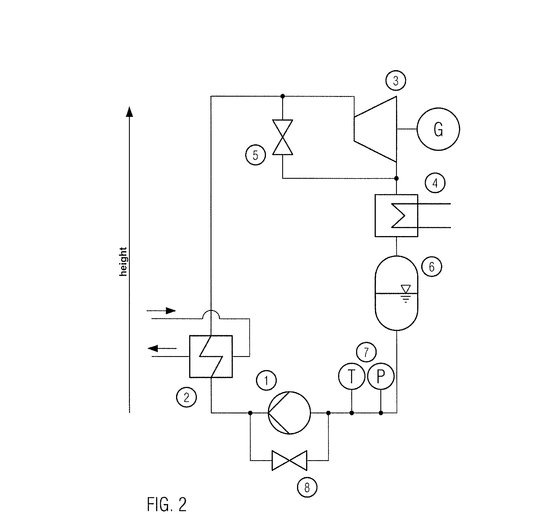
[0039]FIG. 1 shows a thermodynamic cycle apparatus, in particular an ORC system, and the height-ordered arrangement of the main components. The system comprises a feed pump 1 conveying the liquid working medium, with a substantial increase in pressure, to an evaporator 2 where the working medium is evaporated, an expansion machine 3 in which the highly pressurized vapor is expanded whereby mechanical energy is generated. This mechanical energy can be converted into electric energy e.g. through a generator G. From the condenser 4, in which the low pressure vapor coming from the expansion machine 3 is liquefied, the liquid working medium is returned to the feed pump 1 of the system via a possible (optional) storage tank (feed tank) and a suction line.

[0040]In the following, the startup process will be described and it will be explained how the problem is solved by the arrangement described.

[0041]Automatic positioning of the liquid working medium: the plant is to be started from a stan...


PUM


Abstract

The invention relates to a thermodynamic cycle apparatus, comprising: a working medium; an evaporator for evaporating the working medium; an expansion machine for generating mechanical energy while expanding the evaporated working medium; a condenser for condensing the working medium, and a pump for pumping the condensed working medium to the condenser, wherein the geometrical arrangement of the evaporator is selected such that, prior to starting the pump, the condensed working medium can flow from the condenser to the evaporator by force of gravity and the working medium can circulate in a closed circuit via the evaporator and the condenser, whereby in particular a predetermined head height of the liquid working medium can be provided at the pump. The invention additionally relates to a method of starting the thermodynamic cycle apparatus according to the present invention, the method comprising the following steps: applying heat to the evaporator and evaporating the working medium in the evaporator, whereby working medium is caused to flow to the condenser; condensing the working medium in the condenser; starting the pump when a predetermined head height of the working medium at the pump is reached or exceeded.

Description

FIELD OF THE INVENTION[0001]The invention relates to a thermodynamic cycle apparatus, in particular an organic Rankine cycle apparatus, comprising: a working medium; an evaporator for evaporating the working medium; an expansion machine for generating mechanical energy while expanding the evaporated working medium; a condenser for condensing and possibly subcooling the working medium, in particular the working medium expanded in the expansion machine; and a pump for pumping the condensed working medium to the condenser when the thermodynamic cycle apparatus is in operation. The invention additionally relates to a method of starting a thermodynamic cycle apparatus of the type in question.PRIOR ART[0002]An ORC system comprises the following main components: a feed pump conveying the liquid working medium to the evaporator with a substantial increase in pressure, an evaporator in which the working medium is evaporated, an expansion machine in which the highly pressurized vapor is expan...

Claims


Application Information

Patent Timeline
Patent Type & Authority Applications(United States)
IPC IPC(8): F01K13/02F01K13/00F01K11/00
CPCF01K13/02F01K13/006F01K11/00F01K25/08
Inventor SCHUSTER, ANDREASCELIK, ASIMGRILL, ANDREASSPRINGER, JENS-PATRICKGEWALD, DANIELAAUMANN, RICHARD
Owner ORCAN ENERGY AG
Why Eureka
Eureka Blog
Learn More