Image processing device and operation method therefor

Active Publication Date: 2016-08-18
FUJIFILM CORP
View PDF4 Cites 15 Cited by
  • Summary
  • Abstract
  • Description
  • Claims
  • Application Information

AI Technical Summary

Benefits of technology

The invention is a method for processing color images to enhance the color difference and structure of abnormal parts. The method includes steps for inputting a color image signal, acquiring color information, generating a color difference-enhanced image and a frequency component-enhanced image, setting a composition ratio, and composing the two enhanced images to generate a color difference and structure-enhanced image. The technical effect of the invention is to improve image processing capabilities and enhance the detection and identification of abnormal parts in color images.

Problems solved by technology

However, in a case where atrophy has not progressed much, that is, atrophy is progressing (for example, in a case of atrophy included in a group B or a group C in an ABC examination), the difference between an atrophic part and a normal part on an endoscopic image is slight, and it is difficult to determine the degree of progress of atrophy or the boundary between a normal part and a gastritis part in some cases.

Method used


Image

  • Image processing device and operation method therefor
  • Image processing device and operation method therefor
  • Image processing device and operation method therefor

Examples


first embodiment

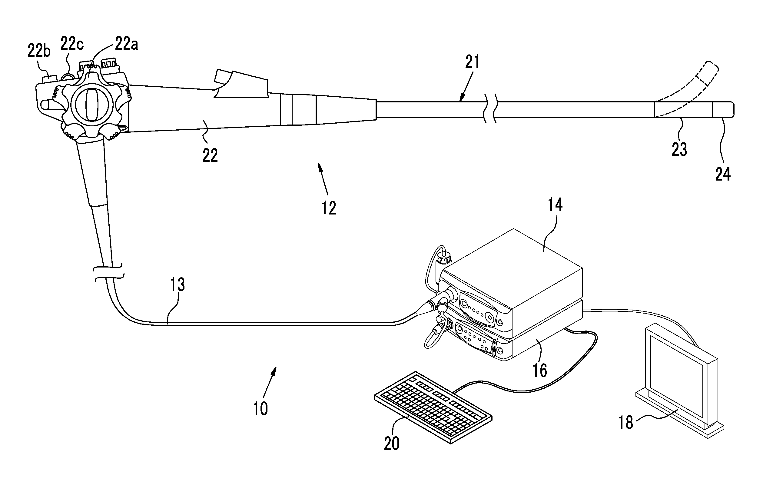
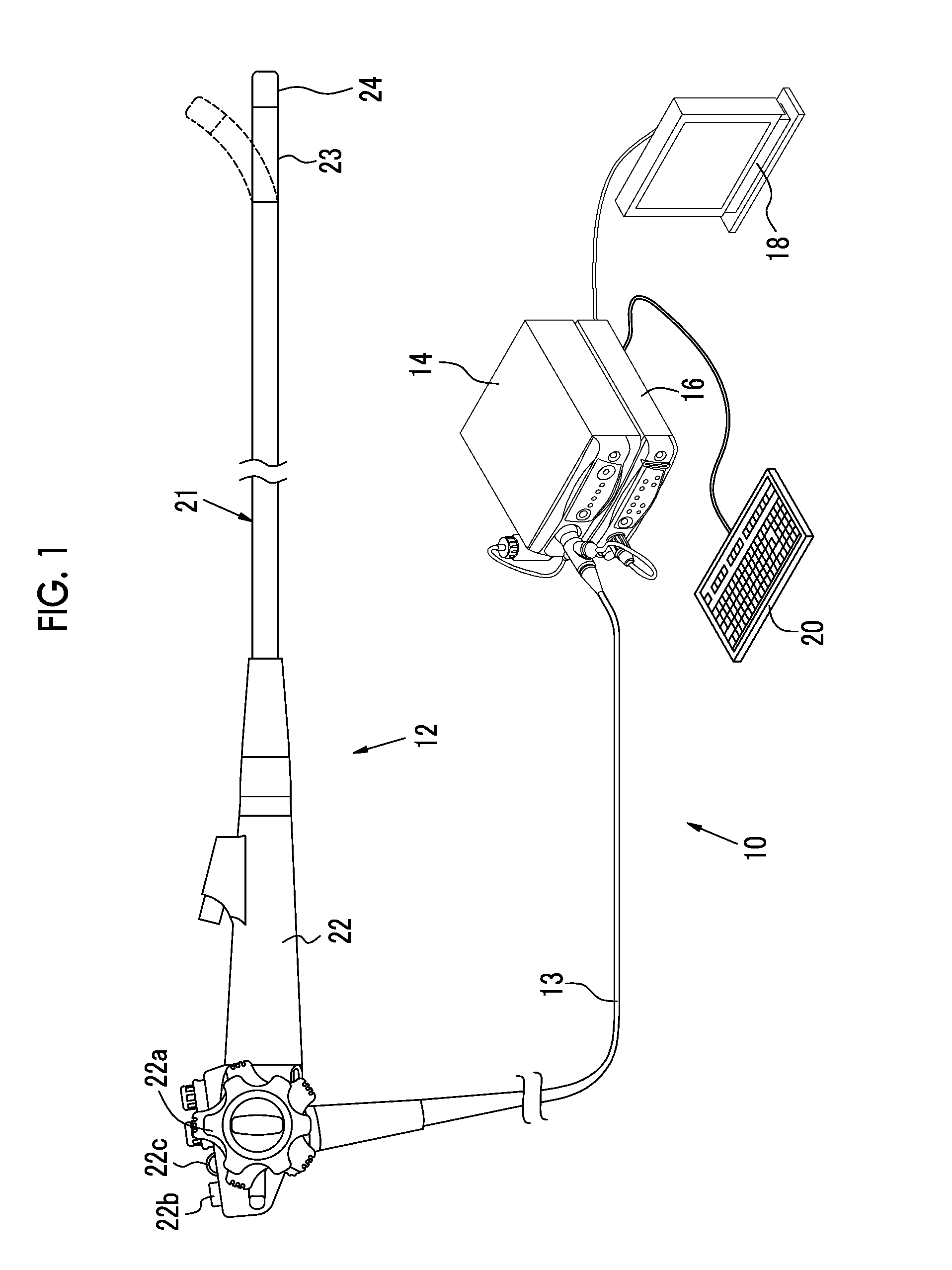
[0043]As shown in FIG. 1, an endoscope system 10 of a first embodiment has an endoscope 12, a light source device 14, a processor device 16, a monitor 18, and a console 20. The endoscope 12 is optically connected to the light source device 14 and electrically connected to the processor device 16 through a universal cord 13. The endoscope 12 has an insertion portion 21 which is inserted into a specimen, an operation portion 22 which is provided in a base portion of the insertion portion, and a bending portion 23 and a tip portion 24 which are provided on the tip side of the insertion portion 21. The bending portion 23 is bent by operating an angle knob 22a of the operation portion 22. The tip portion 24 is directed in a desired direction with a bending operation.

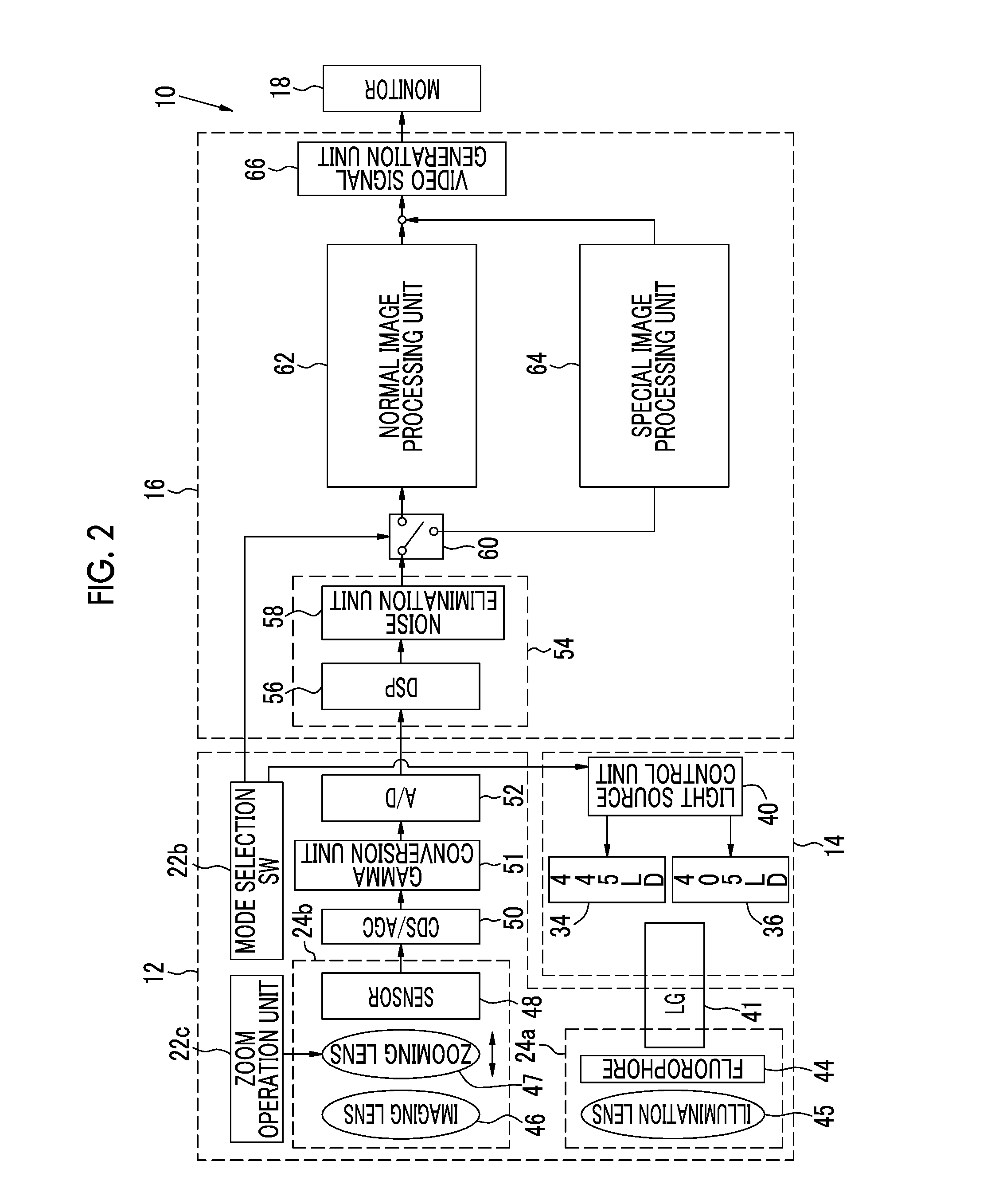
[0044]The operation portion 22 is provided with a mode selection SW 22b and a zoom operation portion 22c, in addition to the angle knob 22a. The mode selection SW 22b is used for a switching operation between two modes of a n...

second embodiment

[0115]In the first embodiment described above, although the RGB image signals are acquired simultaneously with the color sensor, in a second embodiment, the RGB image signals are acquired sequentially with a monochrome sensor. As shown in FIG. 15, a light source device 14 of an endoscope system 200 of the second embodiment is provided with a broadband light source 202, a rotary filter 204, and a filter switching unit 205, instead of the blue laser source 34, the violaceous laser source 36, and the light source control unit 40. The phosphor 44 is not provided in the illumination optical system 24a of the endoscope 12. The imaging optical system 24b is provided with a monochrome sensor 206 with no color filters, instead of the color sensor 48. Other parts are the same as those in the endoscope system 10 of the first embodiment.

[0116]The broadband light source 202 is a Xenon lamp, a white LED, or the like, and emits white light having a wavelength band from blue to red. The rotary filt...

third embodiment

[0121]In the endoscope system 10 of the first embodiment, the B image signal which is a narrowband signal including narrowband wavelength information of the blue laser beam and the violaceous laser beam is used to create the special image, and in the endoscope system 200 of the second embodiment, the Bn image signal which is a narrowband signal including narrowband wavelength information of blue narrowband light is used to create the special image; however, in a third embodiment, a blue narrowband image signal is generated by spectral calculation based on a broadband image, such as a white image, and a special image is generated using the blue narrowband image signal.

[0122]In the third embodiment, white light which is broadband light is illuminated instead of special light in the special observation mode of the simultaneous endoscope system 10. As shown in FIG. 17, in a spectral calculation unit 300 provided between the image processing switching unit 60 and the special image proces...


PUM


Abstract

A base image is created from RGB image signals. A B / G ratio between the B image signal and the G image signal is calculated, and a G / R ratio between the G image signal and the R image signal is calculated. A frequency component-enhanced image in which a frequency component corresponding to an abnormal part different from a normal part is enhanced is generated based on the base image. A composition ratio which indicates the ratio for composing the frequency component-enhanced image with the base image is set based on the B / G ratio and the G / R ratio. The frequency component-enhanced image is composed with the base image at the set composition ratio to generate a structure-enhanced image in which the structure of the abnormal part is enhanced.

Description

CROSS-REFERENCE TO RELATED APPLICATIONS[0001]This application is a Continuation of PCT International Application No. PCT / JP2014 / 078046 filed on Oct. 22, 2014, which claims priority under 35 U.S.C §119(a) to Japanese Patent Application No. 2013-222964 filed Oct. 28, 2013. The above application is hereby expressly incorporated by reference, in its entirety, into the present application.BACKGROUND OF THE INVENTION[0002]1. Field of the Invention[0003]The present invention relates to an image processing device which processes an image for use at the time of diagnosis of atrophic gastritis, and an operation method therefor.[0004]2. Description Related to the Prior Art[0005]In a medical field, diagnosis or the like using an endoscope system comprising a light source device, an electronic endoscope, and a processor device has been widely performed. In a recent endoscope system, with high resolution using a high-vision system, such as high sensitivity or an increase in the number of pixels o...

Claims


Application Information

Patent Timeline
IPC IPC(8): G06T7/00A61B1/273G06T7/40A61B1/005A61B1/06A61B1/05A61B5/00A61B1/00
CPCG02B23/24A61B1/00045A61B1/00009G06T2207/10068G06T5/003G06T7/0012G06T2207/10024G06T2207/30092G06T2207/30101A61B1/273A61B1/0676A61B1/05A61B1/0052G06T2207/30096G06T7/408A61B5/4238A61B5/0059A61B5/004H04N7/18A61B1/000094G06T5/73G06T7/90
Inventor KURAMOTO, MASAYUKI
Owner FUJIFILM CORP
Why Eureka
Try Eureka