
Surface grinding device of pavement surface

a technology of surface grinding and pavement surface, which is applied in the direction of roads, roads, construction, etc., can solve the problems of deteriorating or worn pavement surface surface, affecting the maintenance of pavement surfaces, and repairing pavement surfaces. , to achieve the effect of less prone to deterioration, easy dissipation, and small energy consumption

Active Publication Date: 2016-08-18
HEAT ROCK KOHGYO
View PDF0 Cites 12 Cited by
  • Summary
  • Abstract
  • Description
  • Claims
  • Application Information

AI Technical Summary

Benefits of technology

The patent text describes a problem with current surface grinding devices used for repairing pavement surfaces. The devices leave behind scratched surfaces and can cause adhesion issues with new asphalt-mixed material. Additionally, the weight of the grinding body can cause damage to the pavement surface and lead to deterioration of the blades. The invention aims to provide a surface grinding device that overcomes these problems by requiring less energy, being stable over long periods of time, and being able to smoothly grind the surface of the pavement surface without damaging it.

Problems solved by technology

However, a surface of the pavement surface is deteriorated or worn when the pavement surface is used for long periods of time.
Wheel tracks are formed in the pavement surface and flatness thereof is deteriorated.
If a pavement surface is deteriorated or worn, it is necessary to entirely repair the pavement surface.
Therefore, if the rotating drum is rotated while moving the road surface cutting device at low speed, the plurality of cutter bits can scratch a pavement surface and can shave off a deteriorated surface thereof.

Method used


Image

  • Surface grinding device of pavement surface
  • Surface grinding device of pavement surface
  • Surface grinding device of pavement surface

Examples


Embodiment Construction

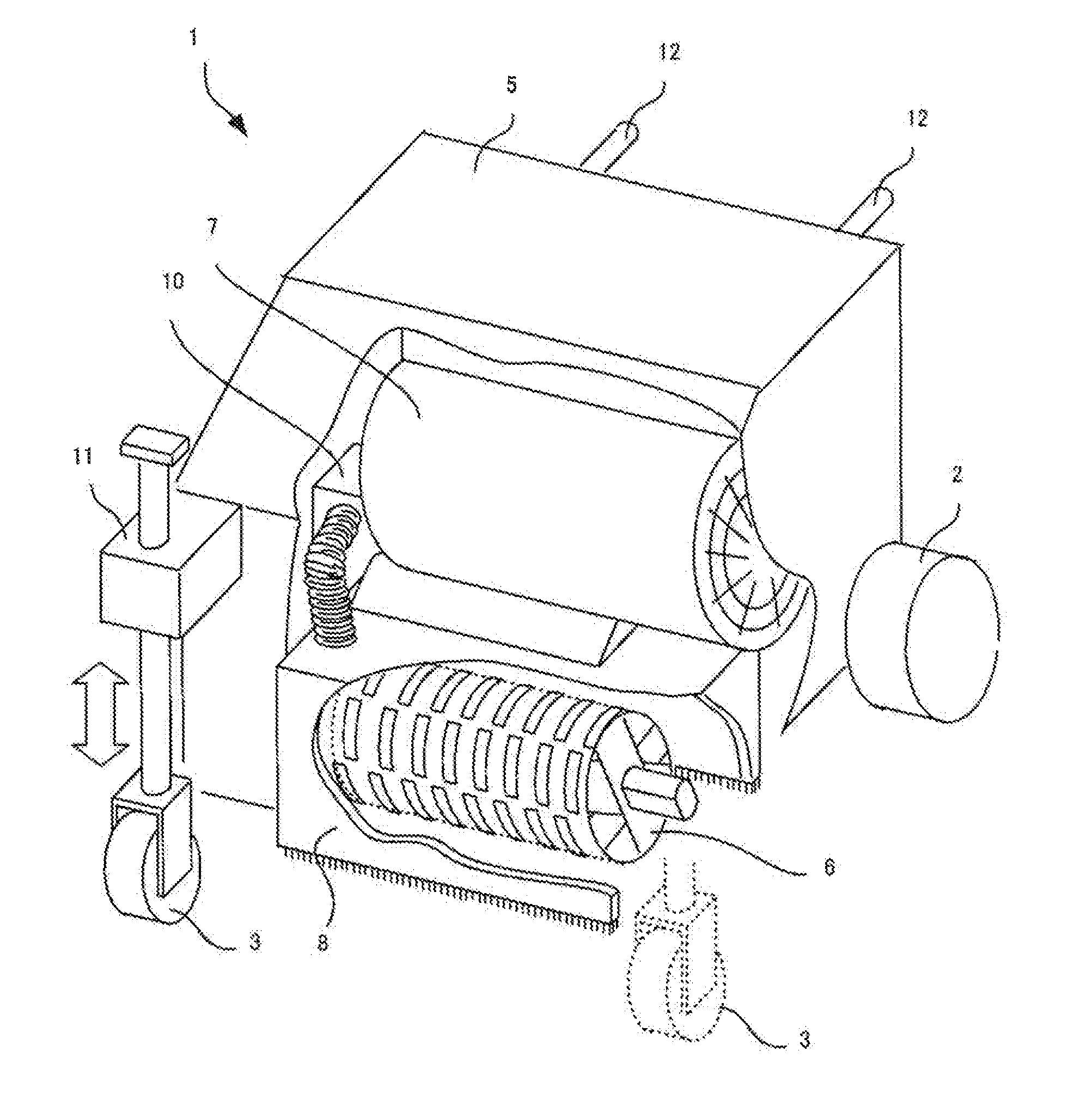
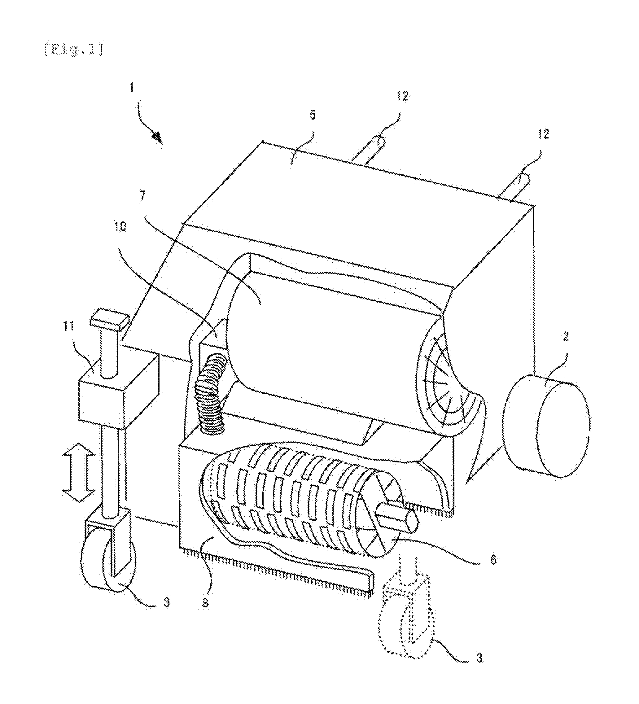
[0021]An embodiment will be described below. As schematically shown in FIG. 1, a surface grinding device 1 of a pavement surface according to the embodiment is composed of a vehicle 5 which runs by means of wheels 2, 3, . . . , a grinding body 6 according to the embodiment of the present invention for grinding the pavement surface, a motor 7 for rotating the grinding body 6, a dust-proof cover 8 which surrounds the grinding body 6 for preventing dispersion of dust which generates when the pavement surface is grinded, and a dust collecting device 10 for sucking and collecting dust. Positions of the rear wheels 2 and 2 of the vehicle 5 are fixed, but heights of the front wheels 3 and 3 can be changed by a height-adjusting mechanism 11. The grinding body 6 will be described in detail. A position of the grinding body 6 is fixed to the vehicle 5, but if the heights of the front wheels 3 and 3 are changed by adjusting the height-adjusting mechanism 11, the height of the grinding body 6 wi...


PUM


Abstract

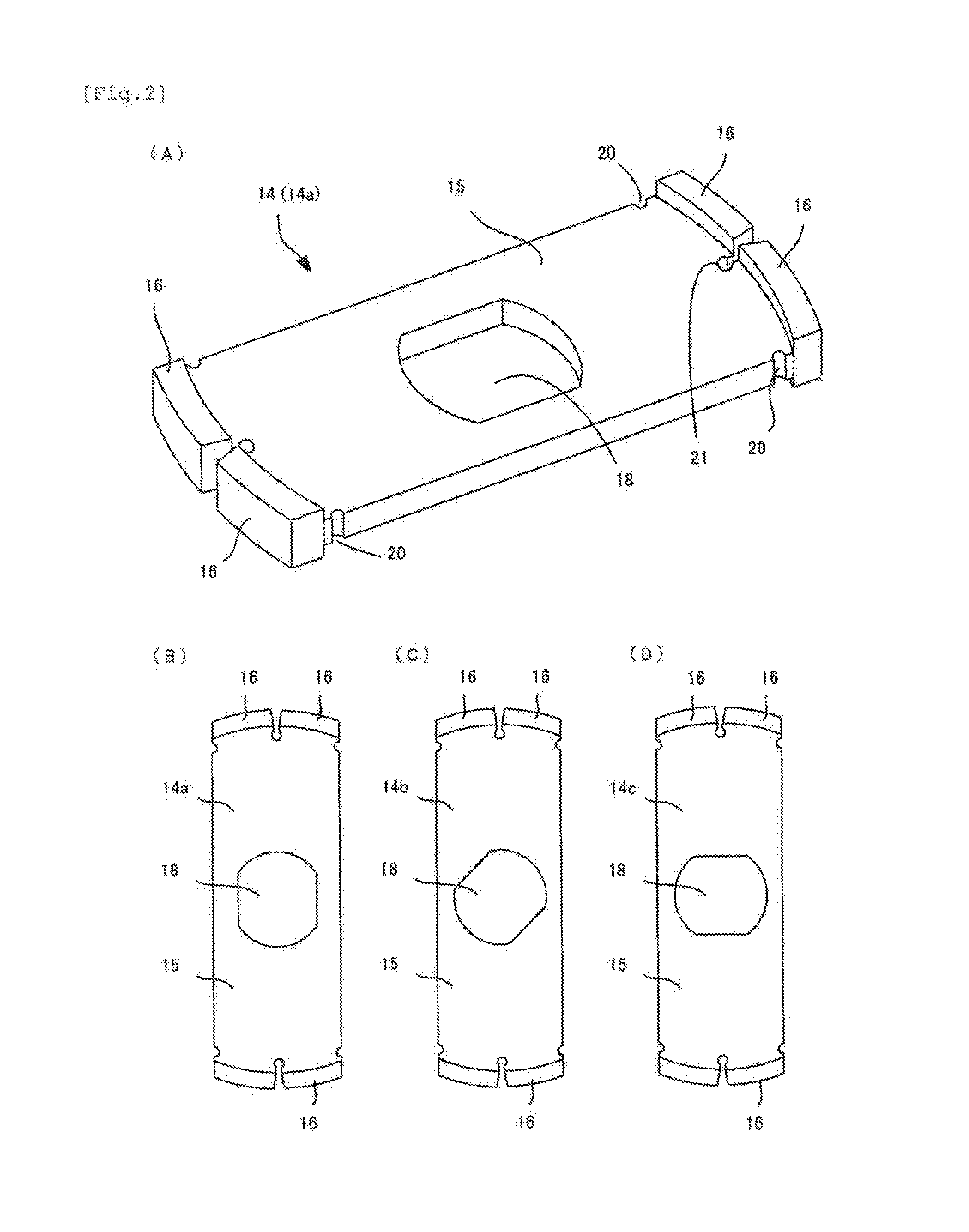
[Object] The present invention provides a surface grinding device of a pavement surface in which driving energy is small, the device can be used for long periods of time, and it is possible to smoothly grind a surface of the pavement surface without damaging the pavement surface.[Solving Means]A grinding body (6) of a surface grinding device (1) of a pavement surface is composed of a rotation shaft (13) and several blades (14). Each of the blades (14) includes a substantially rectangular plate (15) having a predetermined thickness, and arc grinding pieces (16) provided on edges of both short sides of the plate (15). A shaft hole (18) is formed in a center of the plate (15), and the rotation shaft (13) is inserted into the shaft hole (18). In the grinding body (6), the plurality of blades (14) are deviated from and overlap with one another in a rotation direction of the grinding body (6) so that the grinding pieces (16) do not interfere with each other. The grinding piece (16) is thicker than a thickness of the plate (15). When the grinding body (6) rotates and grinds a surface of the pavement surface, widths of the surface grinded by the grinding pieces (16) of the adjacent blades (14) overlap with each other by a predetermined overlap space (26).

Description

TECHNICAL FIELD[0001]The present invention relates to a surface grinding device of a pavement surface which is used for repairing a deteriorated pavement surface and which grinds a surface of the pavement surface.BACKGROUND TECHNIQUE[0002]A pavement surface which is paved by asphalt-mixed material enhances endurance of a road and provides comfortable traveling performance. However, a surface of the pavement surface is deteriorated or worn when the pavement surface is used for long periods of time. Wheel tracks are formed in the pavement surface and flatness thereof is deteriorated. Therefore, it is necessary to appropriately repair the pavement surface. If a pavement surface is deteriorated or worn, it is necessary to entirely repair the pavement surface. In this case, an entire surface of the pavement surface is shallowly shaved off, and deteriorated asphalt-mixed material is removed. Then, the pavement surface is repaved using new asphalt-mixed material thereon. When a relatively ...

Claims


Application Information

Patent Timeline
Patent Type & Authority Applications(United States)
IPC IPC(8): E01C23/088E01C23/12
CPCE01C23/088E01C23/127E01C23/12E01C2301/50
Inventor NISHIDA, HIROYUKI
Owner HEAT ROCK KOHGYO
Learn More