
Liquid discharge apparatus and liquid discharge method

a liquid discharge apparatus and liquid discharge technology, applied in the direction of additive manufacturing processes, manufacturing tools, applying layer means, etc., can solve the problems of streak-like irregularities and streak-like irregularities on the shape three-dimensional objects, and achieve the effect of minimizing the displacement of the landing position of ink droplets, reducing the displacement of the gap length, and facilitating displacemen

Inactive Publication Date: 2016-08-18
MIMAKI ENG
View PDF3 Cites 11 Cited by
  • Summary
  • Abstract
  • Description
  • Claims
  • Application Information

AI Technical Summary

Benefits of technology

The patent text discusses how three-dimensional object shaping apparatuses can improve the process of printing by organizing the placement of nozzles on ink jet heads. By doing so, streaks and unevenness can be avoided, and the ink layers can be more evenly flattened. Additionally, when the apparatus is in two-dimensional printing mode, multi-pass printing can be performed to ensure high-precision printing.

Problems solved by technology

Because of the history, many of the technical aspects so far deemed to be desirable for ink jet printers and 3D printers are, in fact, inconsistent.
A three-dimensional object shaping apparatus such as 3D printer, if equipped with the conventional ink jet heads as exactly as in the known ink jet printers to discharge ink droplets of the object shaping ink, may likely to result in a continuity of ink dots in the main scanning direction, causing streak-like irregularity (mottles) on the shaped three-dimensional object.
When, for example, forming a three-dimensional object using such ink jet heads and an ink of ultraviolet curing type, ink dots may continue into one another in the main scanning direction before being irradiated with ultraviolet light, possibly causing streak-like irregularity.

Method used


Image

  • Liquid discharge apparatus and liquid discharge method
  • Liquid discharge apparatus and liquid discharge method
  • Liquid discharge apparatus and liquid discharge method

Examples


Embodiment Construction

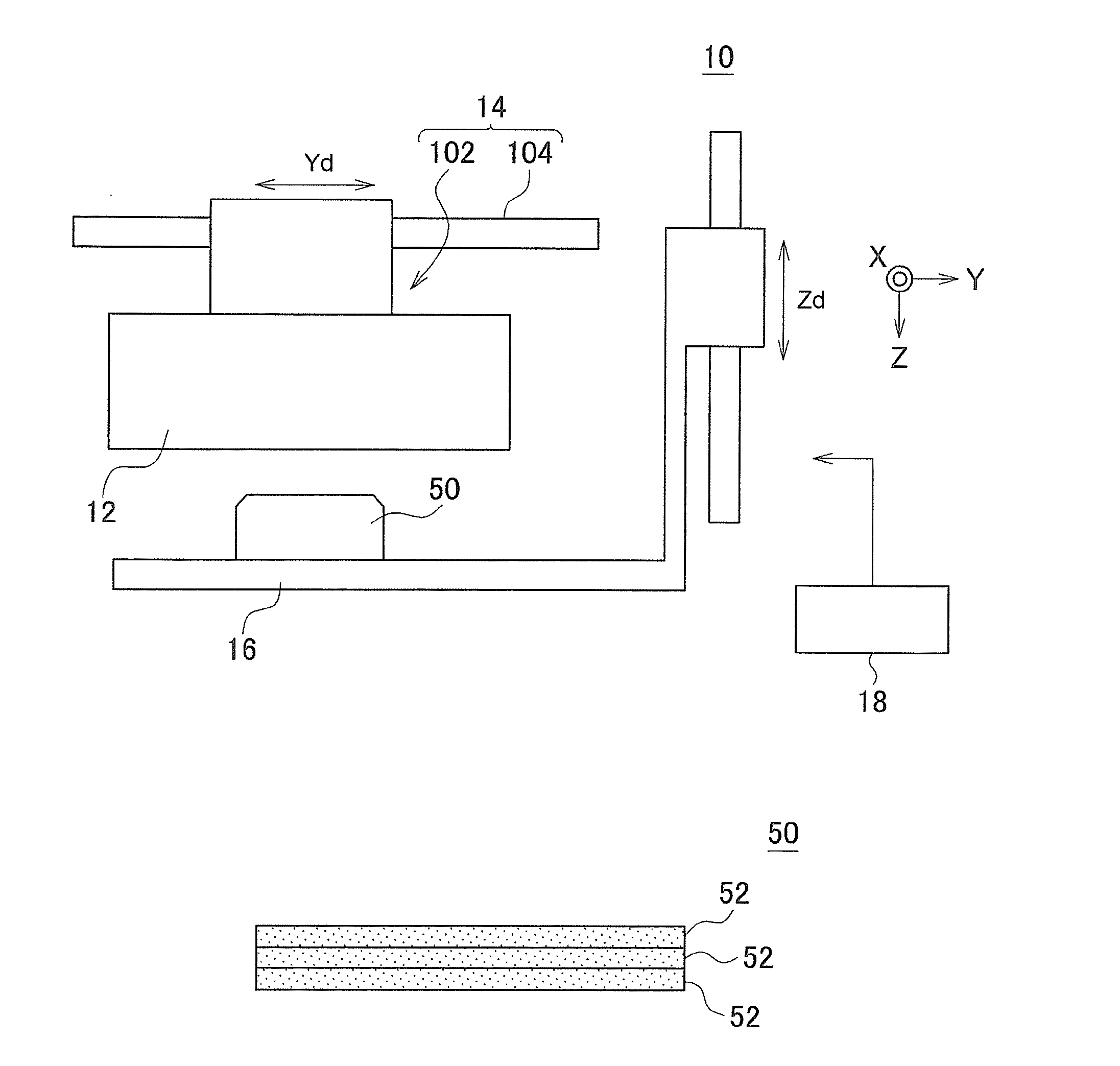
[0091]Hereinafter, an embodiment of this disclosure is described in detail referring to the accompanying drawings. FIGS. 1A to 1C are drawings of an exemplified three-dimensional object shaping apparatus 10 according to an embodiment disclosed herein. FIG. 1A is a drawing of exemplified structural elements in the three-dimensional object shaping apparatus 10. FIG. 1B is a drawing of an exemplified three-dimensional object 50 shaped by the three-dimensional object shaping apparatus 10, schematically illustrating the three-dimensional object 50 currently being shaped.

[0092]The three-dimensional object shaping apparatus 10 described herein shapes the three-dimensional object 50 by means of an additive manufacturing method. The additive manufacturing method refers to a method for shaping the three-dimensional object 50 by stacking on one another a plurality of layers. The three-dimensional object 50 refers to an object having a three-dimensionally formed structure. The three-dimensional...


PUM

PropertyMeasurementUnit
Speedaaaaaaaaaa
Distanceaaaaaaaaaa

Abstract

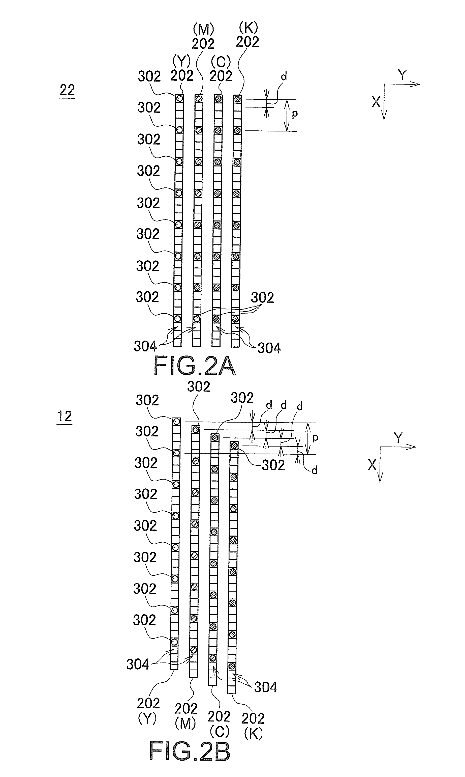
The apparatus includes: a head unit, a main scan driver, and a controller. The head unit has a plurality of nozzle arrays disposed next to one another in a main scanning direction and positions of nozzles in each of the nozzle arrays differ in an orthogonal direction from positions of the nozzles in other nozzle arrays. The controller is configured to set a two-dimensional printing mode and an object shaping mode. The main scan driver regulates a moving speed to a preset first speed and prompts the head unit to perform the main scan at the first speed when the apparatus is in the two-dimensional printing mode and regulates the moving speed at least at a certain timing to a second speed lower than the first speed and prompts the head unit to perform the main scan at the second speed when the apparatus is in the object shaping mode.

Description

CROSS REFERENCE TO RELATED APPLICATIONS[0001]This application claims the priority benefit of Japanese Patent Application No. 2015-026330, filed on Feb. 13, 2015. The entirety of the above-mentioned patent application is hereby incorporated by reference herein and made a part of this specification.TECHNICAL FIELD[0002]This disclosure relates to a liquid discharge apparatus and a liquid discharge method.DESCRIPTION OF THE BACKGROUND ART[0003]In recent years, there is ongoing development of 3D printers designed to form three-dimensional objects. Also, it is being discussed, as an alternative of methods for forming three-dimensional objects, to leverage the technology of known ink jet printers used for color printing of two-dimensional images (for example, refer to the patent document 1). In this instance, ink jet printers (UV printers) may be usable that print objects with inks of ultraviolet curing type (UV inks) (for example, refer to Patent Document 1).[0004]Patent Document 1: JP 20...

Claims


Application Information

Patent Timeline
IPC IPC(8): B29C67/00B41J2/145
CPCB29K2105/0058B29C67/0088B29C67/0085B33Y50/02B33Y30/00B41J19/202B41J2/145B29C67/0059B41J2/15B41J3/4073B33Y10/00B41J3/44B29C64/112B29C64/393B29C64/209B29C64/188
Inventor OHNISHI, MASARU
Owner MIMAKI ENG
Learn More