
Solid polymer power generation or electrolysis method and system

a technology of power generation and polymer, applied in the field of solid polymer power generation or electrolysis method and system, can solve problems such as easy supply of substances, and achieve the effects of reducing carbon dioxide, simplifying equipment for separation, and improving product utilization efficiency

Active Publication Date: 2016-08-04
JAPAN AEROSPACE EXPLORATION AGENCY
View PDF2 Cites 5 Cited by
  • Summary
  • Abstract
  • Description
  • Claims
  • Application Information

AI Technical Summary

Benefits of technology

The solid polymer power generation or electrolysis method described in this patent can reduce carbon dioxide during a reaction while generating electricity by a fuel cell reaction with carbon dioxide used as an oxidizing agent, and obtain the hydrocarbon as a direct product from the fuel cell, without the need for injection of energy from the outside or a high-temperature environment. This method can lead to improved efficiency in producing useful hydrocarbons and simplifying equipment for separation and recovery. This can be useful in removing carbon dioxide from closed environments where manned activity occurs and recovering carbon resources. Furthermore, controlling the reactor temperature, humidification degree, or carbon dioxide and hydrogen supply can allow for more precise control over the production of hydrocarbons.

Problems solved by technology

In addition, in a completely closed environment such as a space station or a rocket, it is not easy to supply substances, and it is necessary to minimize the supply or emission at an element level.
However, each of these methods is a method that injects a large amount of energy for the burial or a method that requires energy for maintaining the high temperature.

Method used


Image

  • Solid polymer power generation or electrolysis method and system
  • Solid polymer power generation or electrolysis method and system
  • Solid polymer power generation or electrolysis method and system

Examples


first embodiment

[0098]A first embodiment of a solid polymer power generation or electrolysis system according to the present invention will be described based on the drawings.

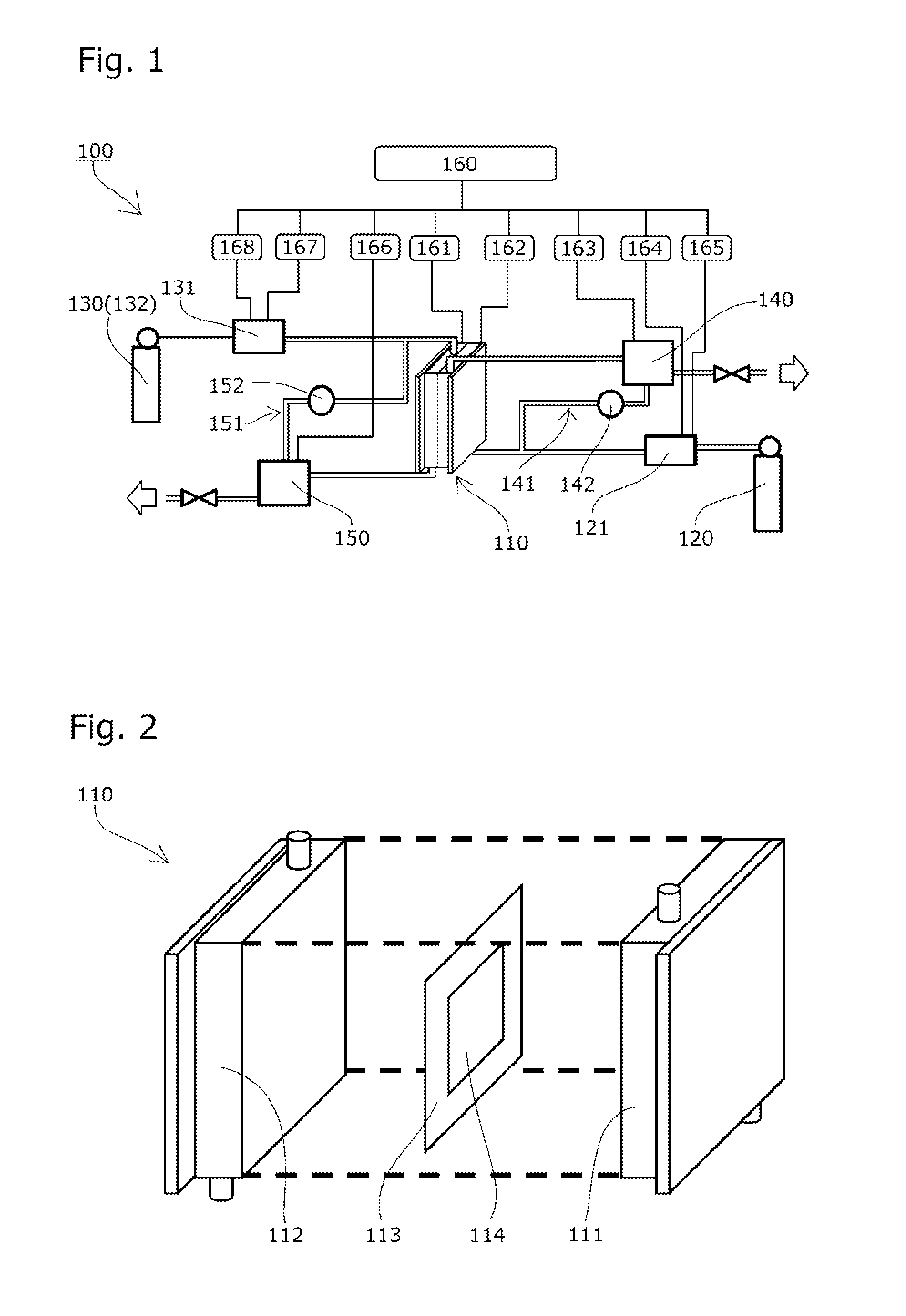
[0099]As shown in FIGS. 1 and 2, a solid polymer power generation or electrolysis system 100 includes a reactor 110 that has a membrane electrode assembly 113 provided with a catalyst layer 114, carbon dioxide supply means 120 for supplying carbon dioxide to the side of a cathode 111 of the reactor 110, hydrogen supply means 130 for supplying hydrogen to the side of an anode 112 of the reactor 110, and gas-liquid separation means 140 and 150 for separating and recovering a product.

[0100]Note that the reactor 110 is simplified and the reactor 110 having only one cell is shown for description, but the actual shape thereof is not limited thereto, and it is desirable to dispose a plurality of cells in series so as to form a stack in order to obtain a high power generation voltage as the entire reactor 110.

[0101]Humidification mean...

second embodiment

[0134]Hereinbelow, a second embodiment in which the voltage is applied between the electrodes will be described by using FIGS. 1 and 2.

[0135]In the case where the voltage is applied between one electrode 111 and the other electrode 112, electric power is supplied from a power supply section that is not shown, and the applied voltage between the electrode 111 and the electrode 112 of the reactor 110 can be configured to be controllable by the voltage control means 161.

[0136]Further, the temperature of the reactor 110 is preferably configured to be controllable by the reactor temperature control means 162.

[0137]The humidification means 121 for supplying water for humidification is connected to the path from the carbon dioxide supply means 120 to the reactor 110.

[0138]Water supply means is configured to supply water or water vapor to the reactor 110 by humidifying a carrier gas supplied from carrier gas supply means 132 using the humidification means 131.

[0139]The gas-liquid separation...

third embodiment

[0149]Next, a third embodiment in which the voltage is applied between the cathode and anode will be described based on FIG. 13.

[0150]A solid polymer power generation or electrolysis system 100a according to the third embodiment is configured without using the carrier gas and, as shown in FIG. 13, the reactor 110, the carbon dioxide supply means 120, and the gas-liquid separation means 140 are the same as those of the solid polymer power generation or electrolysis system 100 according to the second embodiment.

[0151]The water supply means 130 is configured to adjust the temperature of water supplied from a water storage section 133 using heating means 134 and supply the water to the reactor 110 as water vapor.

[0152]Product separation means 170 has the circulation path 151 through which unreacted water or water vapor is circulated to the path from the water supply means 130 to the reactor 110 again, and the circulation pump 152 is provided in the circulation path 151.

[0153]Electric po...


PUM

PropertyMeasurementUnit
temperatureaaaaaaaaaa

Abstract

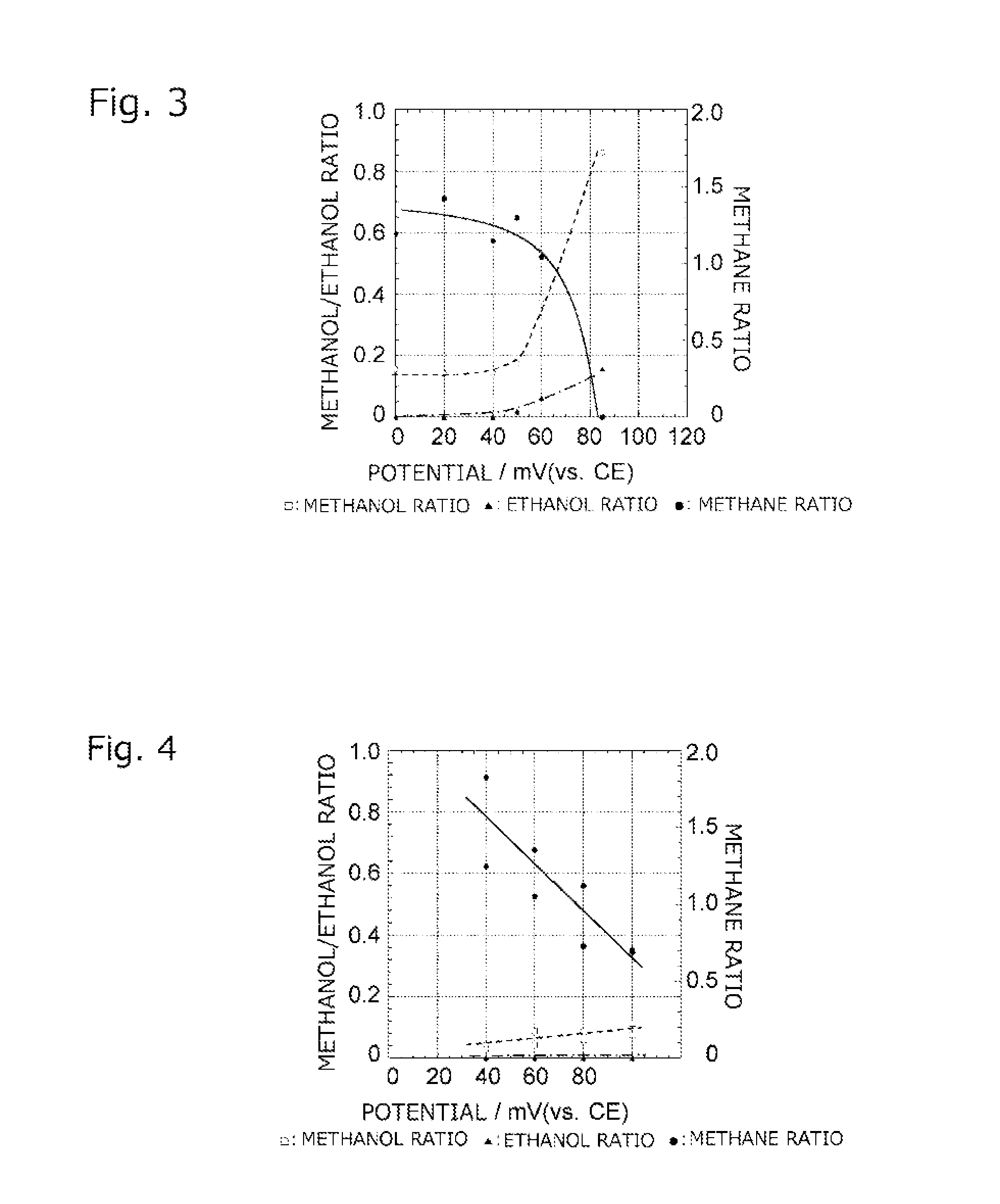
There are provided: a solid polymer power generation or electrolysis method that does not require injection of energy from the outside and maintenance of a high temperature, and is capable of converting carbon dioxide to a useful hydrocarbon while producing energy, controlling the production amounts of the hydrocarbons or the like and a ratio sorted by kind of the hydrocarbons, improving utilization efficiency of a product, and simplifying equipment for separation and recovery; and a system for implementing the solid polymer power generation or electrolysis method. Carbon dioxide is supplied to the side of one electrode 111 of a reactor 110 having a membrane electrode assembly 113, hydrogen is supplied to the side of the other electrode 112, and the amounts of the hydrocarbons produced per unit time and the ratio sorted by kind of the hydrocarbons are changed by controlling a power generation voltage of the reactor 110.

Description

TECHNICAL FIELD[0001]The present invention relates to a solid polymer power generation method and system that supplies carbon dioxide to one of electrodes of a membrane electrode assembly provided with a catalyst layer and supplies hydrogen, water vapor, or liquid water to the other electrode to generate electric power and also produce a hydrocarbon and water, or a solid polymer electrolysis method and system that performs electrolysis and produces a hydrocarbon.BACKGROUND ART[0002]In recent years, since carbon dioxide emission to the atmosphere resulting from combustion of fossil fuels may significantly affect an ecosystem and the global environment, a reduction in the emission of carbon dioxide is desired globally.[0003]Accordingly, a technique for eliminating the emission of carbon dioxide or reducing the emission amount of carbon dioxide is developed and, as part of the development, a technique for fixing carbon dioxide and a technique for converting carbon dioxide to other comp...

Claims


Application Information

Patent Timeline
Patent Type & Authority Applications(United States)
IPC IPC(8): H01M8/1007H01M8/1011H01M8/0656H01M8/06H01M8/2495H01M8/241H01M8/2457H01M8/2455H01M16/00H01M8/04828H01M8/04701H01M8/04089C25B3/02C25B1/02C25B1/00C25B13/08H01M8/1018C25B3/23C25B3/25C25B9/23
CPCC25B3/04H01M8/2495H01M2008/1095C25B15/08C25B9/10Y02E60/528Y02E60/523H01M16/003H01M2300/0082H01M8/2455H01M8/241H01M8/1018H01M8/1011H01M8/0656H01M8/06H01M8/04873H01M8/04835H01M8/04701H01M8/04097C25B13/08C25B3/02C25B1/02C25B1/00H01M8/1007H01M8/2457H01M8/184C25B1/04C25B5/00Y02E60/36Y02E60/50C25B3/25C25B3/23C25B9/23
Inventor SONE, YOSHITSUGUSAKURAI, MASATOSHIMA, ASUKAUMEDA, MINORUNAKABEPPU, TETSUYASHINOZAKI, RYOTAKINOSHITA, TORU
Owner JAPAN AEROSPACE EXPLORATION AGENCY
Learn More