
Opto-electronic module including a non-transparent separation member between a light emitting element and a light detecting element

Active Publication Date: 2016-07-28
AMS SENSORS SINGAPORE PTE LTD
View PDF11 Cites 18 Cited by
  • Summary
  • Abstract
  • Description
  • Claims
  • Application Information

AI Technical Summary

Benefits of technology

The patent text describes how opto-electronic modules can help reduce optical interference and crosstalk, which can improve the signal-to-noise ratio.

Problems solved by technology

Internal interference, on the other hand, can be more challenging to manage, particularly in applications where the proximity sensor is mounted behind a transparent or semi-transparent cover such that the intensity of the light reflected from the cover may be similar in magnitude to the signal of interest.

Method used


Image

  • Opto-electronic module including a non-transparent separation member between a light emitting element and a light detecting element
  • Opto-electronic module including a non-transparent separation member between a light emitting element and a light detecting element
  • Opto-electronic module including a non-transparent separation member between a light emitting element and a light detecting element

Examples


Embodiment Construction

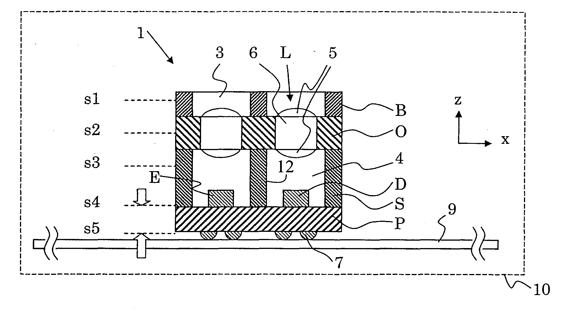
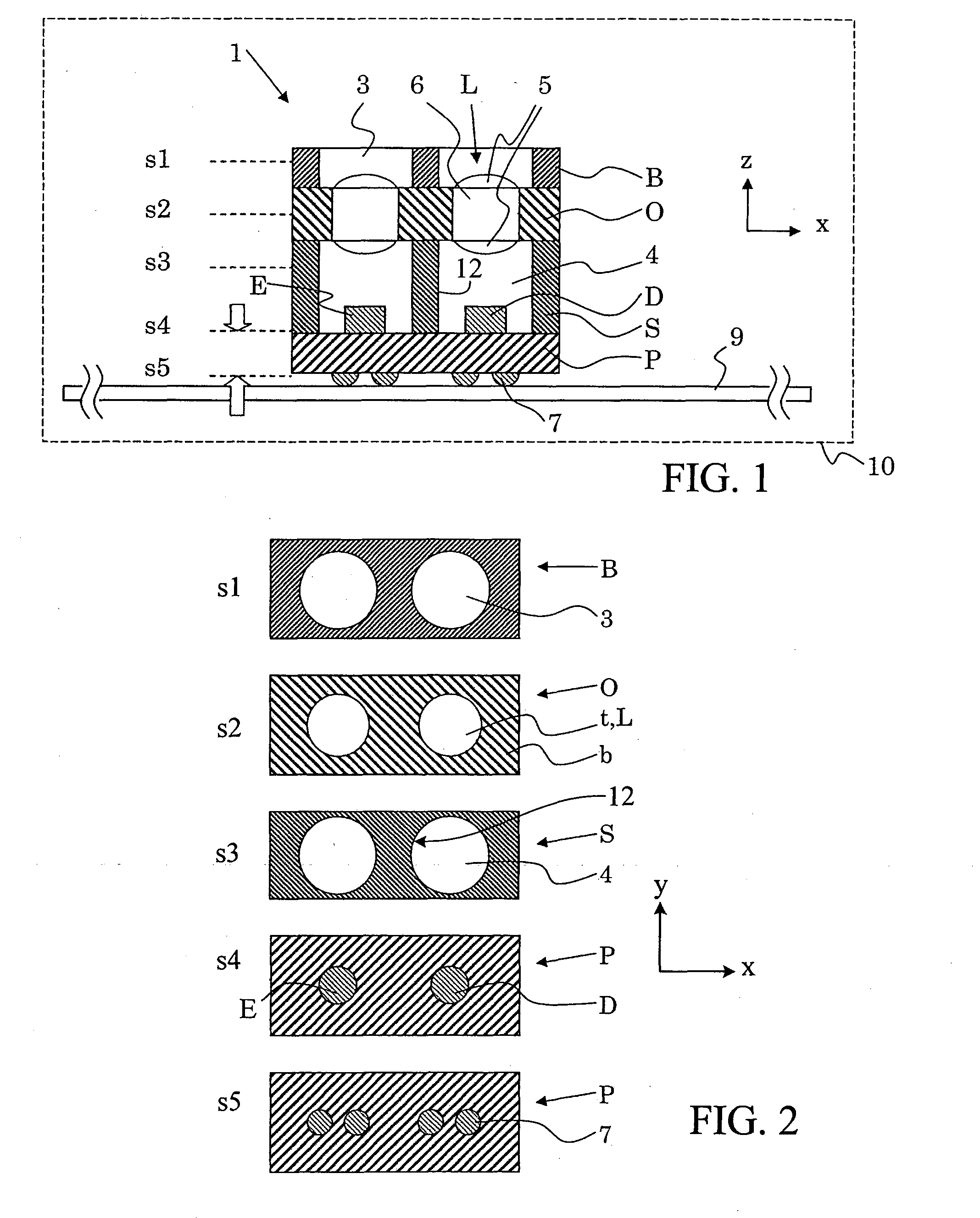
[0018]As illustrated in FIG. 1, an opto-electronic module 1 can include at least one active optical component and at least one passive optical component. Examples of an active optical component include a light sensing or a light emitting component, such as a photodiode, an image sensor, an LED, an OLED or a laser chip. Examples of a passive optical component include an optical component that redirects light by refraction and / or diffraction and / or reflection such as a lens, a prism, a mirror or an optical system (e.g., a collection of passive optical components that may include mechanical elements such as aperture stops, image screens or holders). FIG. 2 shows various lateral schematic cross-sectional views of constituents of the module of FIG. 1, wherein the approximate positions of these lateral cross-sections are indicated in FIG. 1 by s1 to s5 and dashed lines. For s4 and s5, the direction of view is indicated by arrows.

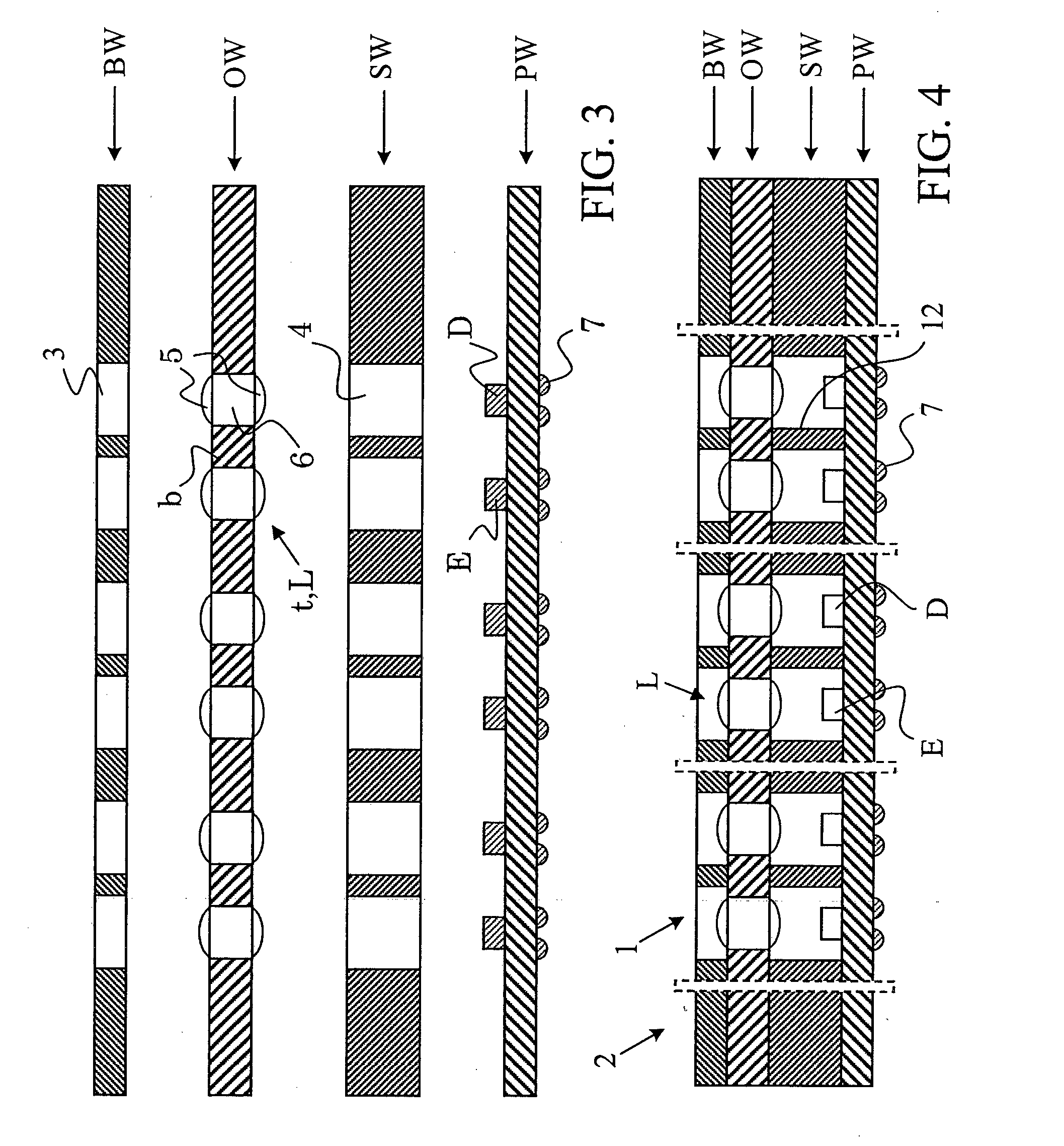
[0019]Module 1 includes several constituents (P, S, O, B) st...


PUM


Abstract

An opto-electronic sensor module (e.g., an optical proximity sensor module) includes a substrate, a light emitter mounted on a first surface of the substrate, the light emitter being operable to emit light at a first wavelength, and a light detector mounted on the first surface of the substrate, the light detector being operable to detect light at the first wavelength. The module includes an optics member disposed substantially parallel to the substrate, and a separation member disposed between the substrate and the optics member. The separation member may surround the light emitter and the light detector, and may include a wall portion that extends from the substrate to the optics member and that separates the light emitter and the light detector from one another. The separation member may be composed, for example, a thermosetting polymer material, a UV-curing polymer material or a visible light-curing polymer material, wherein the separation member further includes one or more inorganic fillers and / or dyes that make the separation member substantially non-transparent to light detectable by the light detector and / or emitted by the light emitter.

Description

TECHNICAL FIELD[0001]This disclosure relates to opto-electronic modules such as optical proximity sensor modules.BACKGROUND[0002]Proximity sensors are used to detect the position or location of an object. Various types of proximity sensors are available, including optical, inductive and capacitive sensors.[0003]Optical proximity sensors can employ reflective techniques, for example, to detect the presence or absence of an object in the vicinity of the sensor. A typical technique is to use a light emitting diode (LED) and an optical detector configured in such a way that light emitted from the LED is reflected from an object back to the detector. The light source can be selected so that the light is suitable for detection by the light detector. Thus, for example, the light source can generate light of a frequency that the light detector is best able to detect and that is not likely to be generated by other nearby sources.[0004]In designing small optical proximity, issues of electrica...

Claims


Application Information

Patent Timeline
IPC IPC(8): G01D5/40G02B5/22G02B5/20F21Y101/00
CPCG01D5/40G02B5/223G02B5/208B29D11/00307B29D11/00375G02B6/4204G02B6/4246G02B6/4249G03B7/099H01L27/14625H01L27/14678H01L2924/0002H01L2924/00
Inventor RUDMANN, HARTMUTBIETSCH, ALEXANDERWESTENHOFER, SUSANNEGUBSER, SIMONLAFFRANCHINI, SAMUELE
Owner AMS SENSORS SINGAPORE PTE LTD
Learn More