
Electrical storage system

a technology of electric storage and storage system, which is applied in the direction of charging stations, battery/fuel cell control arrangements, transportation and packaging, etc., can solve the problems of the device burdening the user with an excessive electricity cost, so as to reduce the required electricity cost, the effect of suppressing abnormal hea

Active Publication Date: 2016-07-28
TOYOTA JIDOSHA KK
View PDF2 Cites 13 Cited by
  • Summary
  • Abstract
  • Description
  • Claims
  • Application Information

AI Technical Summary

Benefits of technology

The invention is a system that allows a vehicle to charge its battery with electricity from a commercial power supply. The system also adjusts the temperature of the battery to a comfortable level. The commercial power supply charges the battery at a lower cost in the initial period of usage. The system controls when the battery is charged and operates the temperature adjustment device based on this information. By prioritizing the charging of the battery in the initial period, the system reduces the cost of electricity required to charge the battery. This results in lower energy expenses for the user, regardless of when they start their vehicle.

Problems solved by technology

Such charging of the electrical storage device burdens the user with an excessive cost of electricity.
Such operation of the fan results in burdening the user with an excessive cost of electricity.

Method used


Image

  • Electrical storage system
  • Electrical storage system
  • Electrical storage system

Examples


Embodiment Construction

[0034]Hereinafter, an embodiment of the invention will be described.

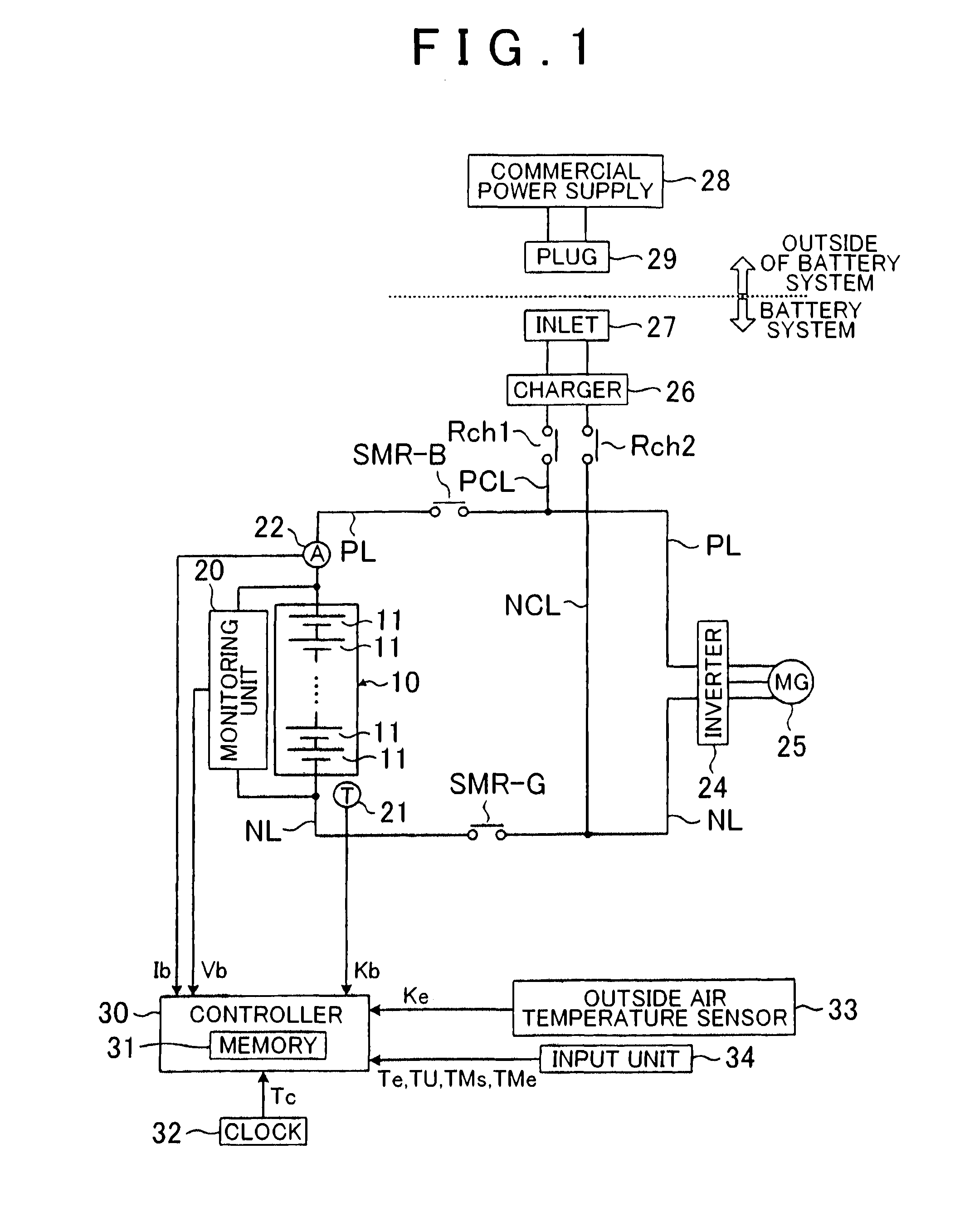
[0035]FIG. 1 is a view that shows the configuration of a battery system (which corresponds to the electrical storage system according to the invention) according to the present embodiment. The battery system shown in FIG. 1 is mounted on a vehicle. The vehicle is, for example, a plug-in hybrid vehicle (PHV) or an electric vehicle (EV).

[0036]The PHV includes not only a battery pack (described later) as a power source for propelling the vehicle but also another power source, such as an engine and a fuel cell. The EV includes only the battery pack (described later) as a power source for propelling the vehicle. In the PHV and the EV, as will be described later, the battery pack is allowed to be charged with electric power from a commercial power supply.

[0037]The battery pack 10 includes a plurality of serially connected single cells 11. An alkaline secondary battery, such as a nickel-metal hydride battery and a nickel-c...


PUM


Abstract

Charging of an electrical storage device is completed by operation-starting time while increasing a percentage of a charging time of the electrical storage device in a first time period as compared to a percentage of the charging time in a second time period when the first time period and the second time period are included within a period from when a user sets the operation-starting time to the operation-starting time. A temperature adjustment device is operated such that a temperature of the electrical storage device at the operation-starting time falls within a target temperature range while increasing a percentage of an operating time of the temperature adjustment device in the first time period as compared to a percentage of the operating time in the second time period when the first time period and the second time period are included within the period from when the user sets the operation-starting time to the operation-starting time. The operation-starting time is scheduled time at which a start-up of a vehicle is initiated.

Description

BACKGROUND OF THE INVENTION[0001]1. Field of the Invention[0002]The invention relates to an electrical storage system that charges an electrical storage device with electric power from a commercial power supply and that adjusts the temperature of the electrical storage device.[0003]2. Description of Related Art[0004]In Japanese Patent Application Publication No. 2011-259672 (JP 2011-259672 A), an electrical storage device is charged from an external power supply, a user is allowed to set time at which the charging is completed (referred to as charging completion time). When the charging completion time is set, the electrical storage device is charged such that charging of the electrical storage device completes at the charging completion time. In JP 2011-259672 A, in order to bring the temperature of the electrical storage device at the charging completion time into a predetermined temperature range, a fan for cooling the electrical storage device is operated until the charging comp...

Claims


Application Information

Patent Timeline
Patent Type & Authority Applications(United States)
IPC IPC(8): B60L11/18H02J7/00H02J7/02
CPCB60L11/1816B60L11/187B60L11/184B60L2240/545B60L2240/80B60L2250/14B60L2260/56B60L2260/58Y02T10/7072Y02T90/14Y04S30/14B60L53/14B60L53/64B60L58/24B60L58/26B60L58/27Y02T10/70Y02T90/12Y02T90/167Y02T90/16
Inventor MURATA, TAKASHIOMI, YASUMITSUYAMANAKA, TAKASHITAKEUCHI, MASAYUKI
Owner TOYOTA JIDOSHA KK
Learn More