
Lighting device comprising at least two sets of LEDs

a technology of led light source and led light source, which is applied in the direction of semiconductor devices for light sources, light and heating apparatus, fixed installation, etc., can solve the problems of low cri (“color rendering index”) of the generated light, the light output of the amber led light source is relatively large, and the controller is required relative to complicated, etc., to achieve good color mixing

Active Publication Date: 2016-07-21
SIGNIFY HLDG BV
View PDF2 Cites 20 Cited by
  • Summary
  • Abstract
  • Description
  • Claims
  • Application Information

AI Technical Summary

Benefits of technology

This patent describes a lighting device with two sets of LEDs that produce blue light at different wavelength ranges. By using blue light with longer wavelengths, the device's color rendering index (CRI) can be improved. The device also allows for independent control of the LEDs and the use of discrete luminescent elements to achieve better color mixing without additional barriers between the LEDs. The technical effects of this patent include improved CRI and better color mixing in a lighting device.

Problems solved by technology

It is a disadvantage of the known LED-based lighting devices that in order to achieve the BBL dimming effect a relatively complicated controller is required for controlling the light output level of the normal LED light sources and that of the amber LED light source, as it has to be determined what the required output levels should be in order to achieve the BBL dimming effect.
It is a further disadvantage of the known LED-based lighting devices that the light output of the amber LED light source shows a relative large decrease at increasing temperature of the LED, which is in particular disadvantageous in applications where light of a high brightness, e.g. spot light applications, is required.
It is another further disadvantage of the known LED-based lighting devices that the CRI (“Color Rendering Index”) of the generated light is relatively low at a color temperature of approximately 2200 K.

Method used


Image

  • Lighting device comprising at least two sets of LEDs
  • Lighting device comprising at least two sets of LEDs
  • Lighting device comprising at least two sets of LEDs

Examples


Embodiment Construction

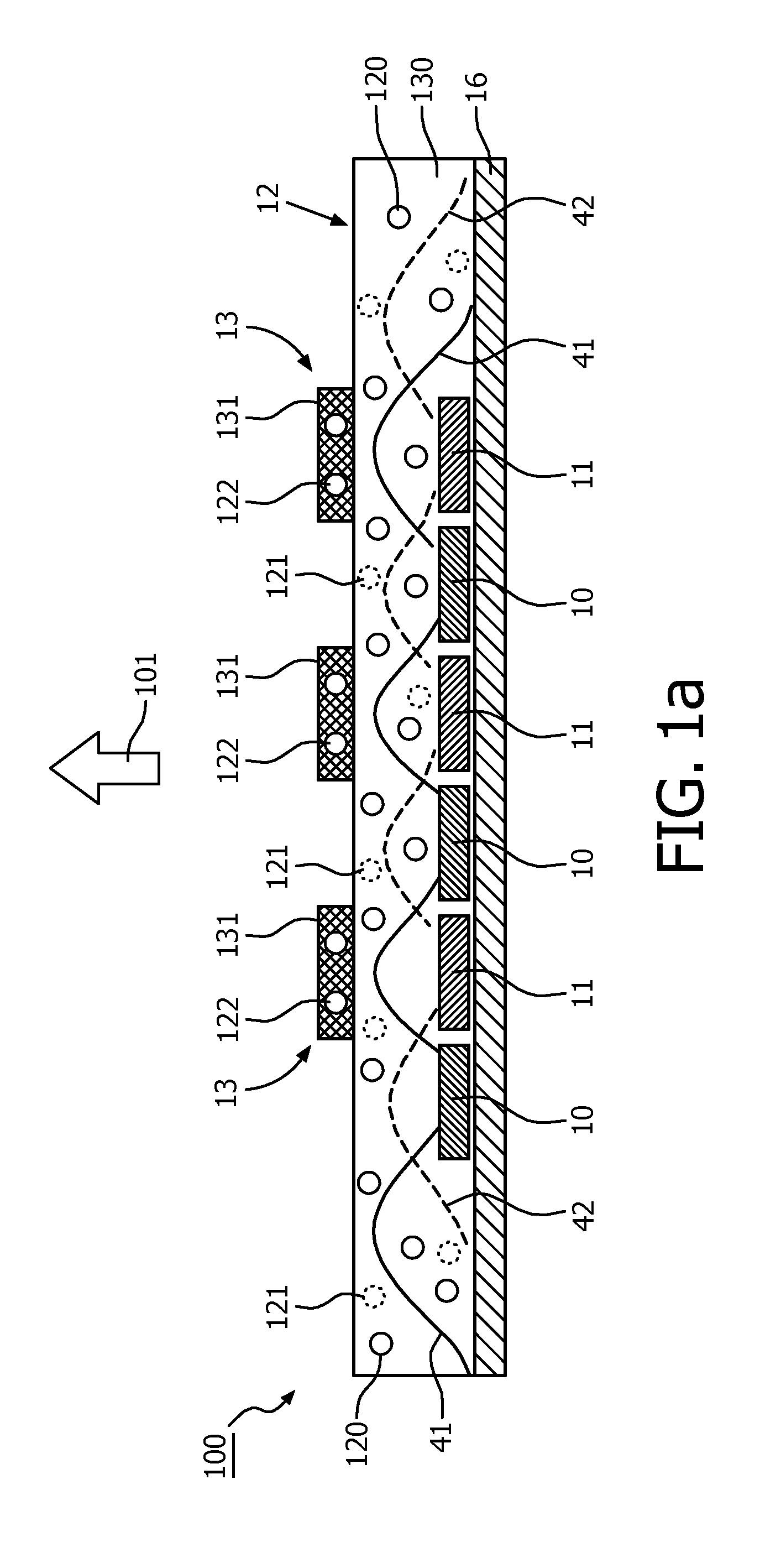
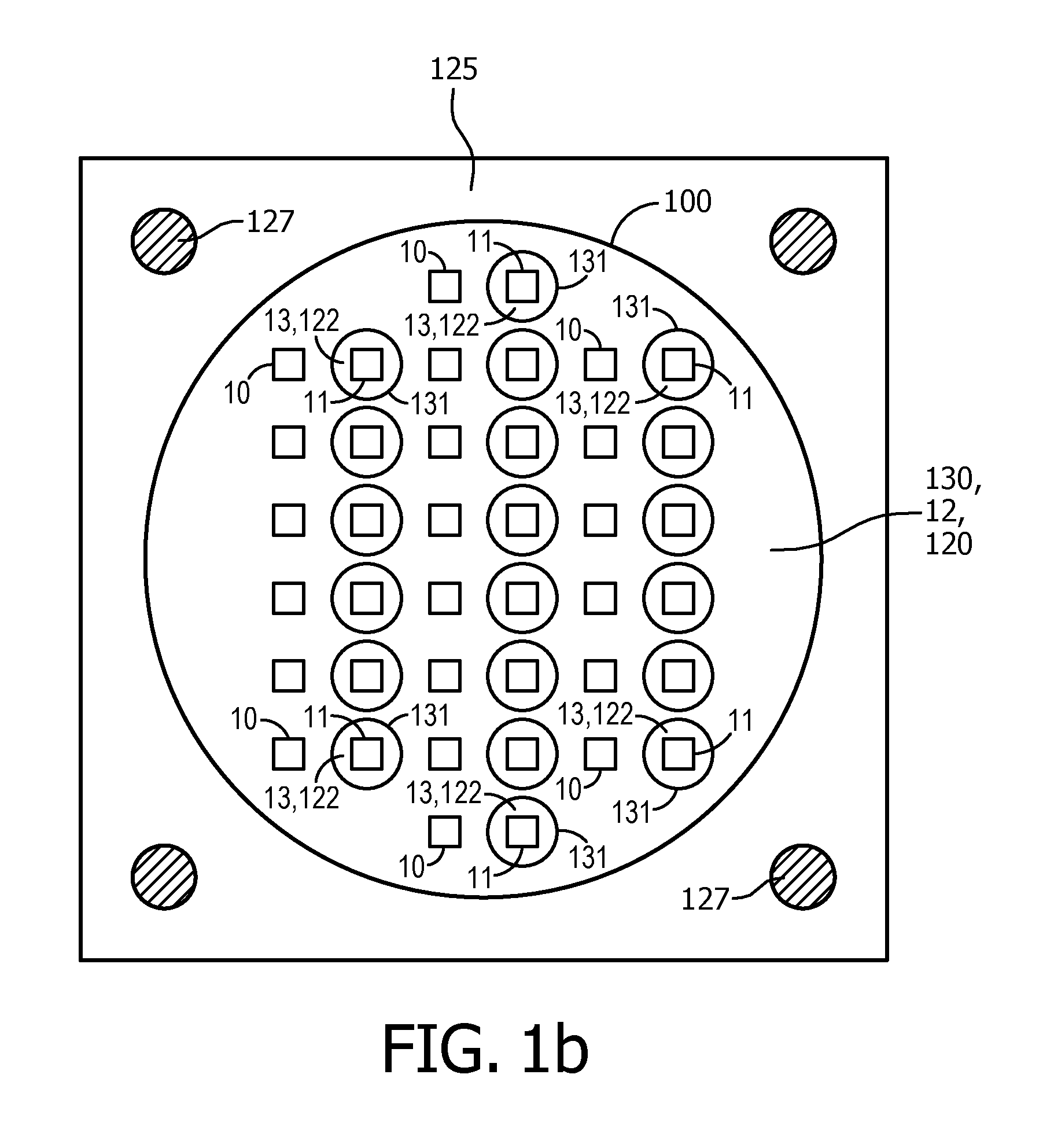
[0046]FIGS. 1a and 1b schematically depict a lighting device 100 comprising a first set of LEDs 10, a second set of LEDs 11, and first and second luminescent elements 12, 13. The first and second set of LEDs 10, 11 are mounted on a board 16. The first set of LEDs 10 is configured to generate blue light 14 (FIG. 1a) in the wavelength range 440 nm-490 nm during operation of the lighting device 100. The second set of LEDs is configured to generate blue light 15 (FIG. 1a) in the wavelength range 440 nm-490 nm during operation of the lighting device 100. In an alternative embodiment, the blue light 14 is in the wavelength range of 440-465 nm and the blue light 15 is in the wavelength range of 465 nm-490 nm. In another alternative embodiment of the lighting device, the first set of light emitting diodes is arranged to emit blue light in the wavelength range of 440 nm-465 nm, and wherein the second set of light emitting diodes is arranged to emit violet light in the wavelength range of 400...


PUM


Abstract

The invention provides a lighting device (100) comprising a first set of light emitting diodes (10) arranged to emit light (14) in a first wavelength range of 300 nm-490 nm, a second set of light emitting diodes (11) arranged to emit light (15) in a second wavelength range of 300 nm-490 nm, a first luminescent element (12) radiationally coupled to the first and second set of light emitting diodes and arranged to convert at least a part of the light of the first wavelength range and at least a part of the light of the second wavelength range into first luminescent element light, a second luminescent element (13) radiationally coupled to at least a subset of the second set of light emitting diodes and arranged to convert at least a part of the light (15) of the second wavelength range into second luminescent element light, wherein, during operation, the brightness level of the light (14) emitted by the first set of light emitting diodes (10) and the brightness level of the light (15) emitted by the second set of light emitting diodes (11), respectively, is controllable independently of each other and wherein the lighting device is arranged to generate white lighting device light (101).

Description

FIELD OF THE INVENTION[0001]The invention relates to a lighting device comprising at least two sets of light emitting diodes. The invention further relates to a lighting module comprising said lighting device. The invention further relates to a lamp comprising such lighting device. The invention further relates to a luminaire comprising said lighting device or said lighting module. The invention even further relates to a method for producing said lighting device.BACKGROUND OF THE INVENTION[0002]Light Emitting Diode (LED) based lighting devices are being used for many applications. The relatively low power consumption and relatively long lifetime of LEDs make them a very useful alternative for conventional light sources like incandescent lamps or fluorescent tubes. Hence, not only new-designed lighting equipment often utilizes LEDs, but in many markets LED products are being used to replace other light sources like incandescent or halogen light sources, for instance. These so-called ...

Claims


Application Information

Patent Timeline
Patent Type & Authority Applications(United States)
IPC IPC(8): H05B33/08F21K99/00F21V9/16H05B44/00
CPCH05B33/086F21Y2101/02F21K9/56F21V9/16H01L25/0753H01L33/504C09K11/0883C09K11/7774F21S8/06H01L2224/48091F21K9/64F21Y2115/10H05B45/20F21V9/40F21V13/08F21V9/38F21V9/32H05B45/3574C09K11/77348H01L2924/00014
Inventor PEETERS, MARTINUS PETRUS JOSEPHWEGH, RENE THEODORUSDUMOULIN, RAIMOND LOUISVAN DER LUBBE, MARCELLUS JACOBUS JOHANNES
Owner SIGNIFY HLDG BV
Learn More