
Illumination source providing enhanced color mixing

a technology of illumination source and color mixing, which is applied in the direction of discharge tube/lamp details, discharge tube luminescnet screen, discharge tube/lamp details, etc., can solve the problems of increasing manufacturing costs, currently known techniques that fail to provide cost effective illumination sources with the required light intensity and color mixing, etc., and achieves enhanced color mixing and cost effective effects

Active Publication Date: 2008-06-12
BOE TECH GRP CO LTD
View PDF40 Cites 20 Cited by
  • Summary
  • Abstract
  • Description
  • Claims
  • Application Information

AI Technical Summary

Benefits of technology

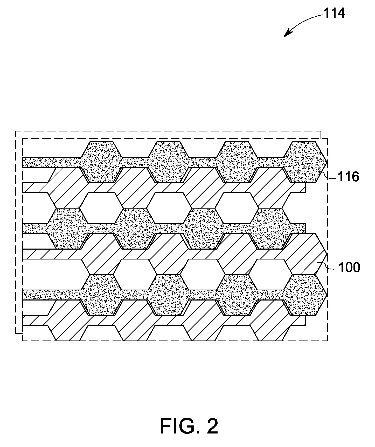
[0008]These and other features, aspects, and advantages of the present invention will become better understood when the following detailed description is read with reference to the accompanying drawings in which like characters represent like parts throughout the drawings, wherein:
[0009]FIG. 1 is a schematic representation of a top view of an OLED layer segment in one embodiment of the present invention.

Problems solved by technology

However, reducing the pixel size can significantly increase the cost of manufacturing due to extra pixels / area.
Currently known techniques fall short of providing cost effective illumination sources with the required light intensity and color mixing.

Method used


Image

  • Illumination source providing enhanced color mixing
  • Illumination source providing enhanced color mixing
  • Illumination source providing enhanced color mixing

Examples


Embodiment Construction

[0027]Embodiments of the present invention relate to organic illumination sources for controllable illumination, systems including such organic illumination sources and methods for controlled illumination.

[0028]As used herein, the term “organic illumination source” refers to an organic light emitting device (OLED) illumination source. As used herein, the term “OLED” refers to devices including organic light emitting materials generally, and includes but is not limited to organic light emitting diodes. As used herein, the term “OLED element” refers to the basic light-producing unit of the area illumination sources of the present invention, comprising at least two electrodes with a light-emitting organic material disposed between the two electrodes. OLED elements may include one or more electroactive layers. As used herein, the term “OLED layer” refers to a light-producing unit including at least one OLED element.

[0029]The term “electroactive” as used herein refers to a material that ...


PUM


Abstract

An illumination source is disclosed. The illumination source includes at least one OLED layer. The OLED layer includes an active light emitting region including a plurality of primary light-emitting OLED elements and secondary light emitting OLED elements connecting each of the plurality of primary light emitting OLED elements to at least another primary light emitting OLED element.

Description

CROSS REFERENCE TO RELATED APPLICATIONS[0001]This application is a continuation-in-part of U.S. patent application Ser. No. 11 / 567,478, entitled “COLOR TUNABLE ILLUMINATION SOURCE AND METHOD FOR CONTROLLED ILLUMINATION”, filed 06 Dec. 2006, which is herein incorporated by reference.BACKGROUND[0002]The invention generally relates to color illumination sources. The invention particularly relates to organic light emitting illumination sources.[0003]Previously disclosed color-tunable illumination devices, in particular white light illumination devices, require mixing of colors (for example, red, green, and blue light) to produce a desired color. Typically, the mixing of light with different colors is achieved with a diffuser film. A distance dependent on the pixel size and the arrangement of pixels has to be maintained between the diffuser and the illumination source in order to achieve a homogeneous appearance of mixed light. Typically, the smaller the pixels, the closer the diffuser d...

Claims


Application Information

Patent Timeline
Patent Type & Authority Applications(United States)
IPC IPC(8): H01J1/63
CPCH01L25/048H01L27/3204H01L27/3209H01L27/3223H01L51/5262H01L51/5281H01L2924/0002H01L2251/5338H01L2251/5361H01L2924/00H10K59/86H10K59/32H10K59/88H10K2102/311H10K59/95H05B33/12H10K50/85H10K50/86H10K59/90
Inventor ROGOJEVIC, SVETLANADUGGAL, ANIL RAJPOON, HAK FEI
Owner BOE TECH GRP CO LTD
Learn More