
Method and apparatus for eye detection from glints

a technology of reflection structure and eye detection, applied in the field of object detection and monitoring, can solve the problems of significant deformation of robustness, difficult to detect eyes in noisy images, and relatively computationally intensive methods

Active Publication Date: 2016-07-21
SEEING MACHINES
View PDF5 Cites 18 Cited by
  • Summary
  • Abstract
  • Description
  • Claims
  • Application Information

AI Technical Summary

Benefits of technology

This patent is about an improved method for detecting objects in images, particularly eyes. The method involves capturing images of an object and analyzing them to identify specific reflections caused by the object. These reflections are then used to determine the position of the object in the image. This can be useful for applications such as video games or security cameras. The patent also describes an image processing system that can detect and track objects in a series of images. The result is a more accurate and efficient way to locate and track objects in images.

Problems solved by technology

Proper detection of eyes in sensed noisy images can be difficult, especially in the presence of glasses with the occlusion generated by their frame and the reflections occurring on the lenses.
This method relies on training a model based on the appearance of the object to be detected and its robustness will degrade significantly in the presence of noise such as strong reflections and / or occlusions.
Further, this method is relatively computationally intensive.
This method relies on the texture of the eyes and its performance will degrade significantly if the iris is partially occluded by specular reflections on the lenses of glasses for example.
Such systems have inherent disadvantages.
The overlap creates additional redundant processing on the same pixel data and can create multiple detections of the same eye from different detectors which require further processing to disambiguate.
In addition, where the eye detector operates on multiple frames and the eye is moving (creating a trajectory), such prior art systems will not be able to resolve a trajectory that moves across the multiple eye detection regions.

Method used


Image

  • Method and apparatus for eye detection from glints
  • Method and apparatus for eye detection from glints
  • Method and apparatus for eye detection from glints

Examples


Embodiment Construction

[0033]The preferred embodiment provides a robust form of eye detection through the utilisation of the corneal reflection in a captured image. As the corneal reflection from the eye is usually still present, even in the presence of other strong reflections and noise, the detection and processing of corneal reflection location can provide a strong indicator of eye position and gaze.

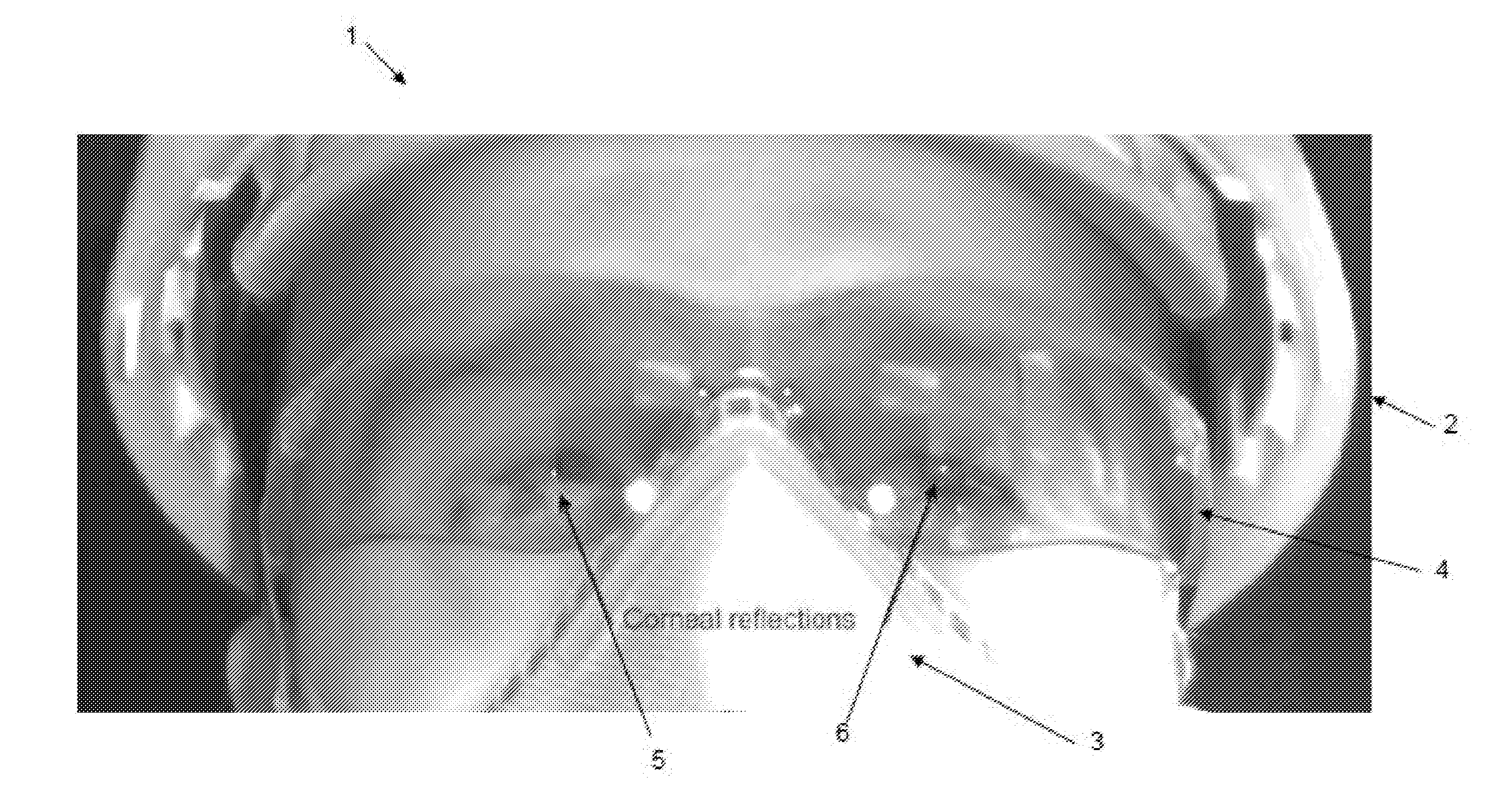
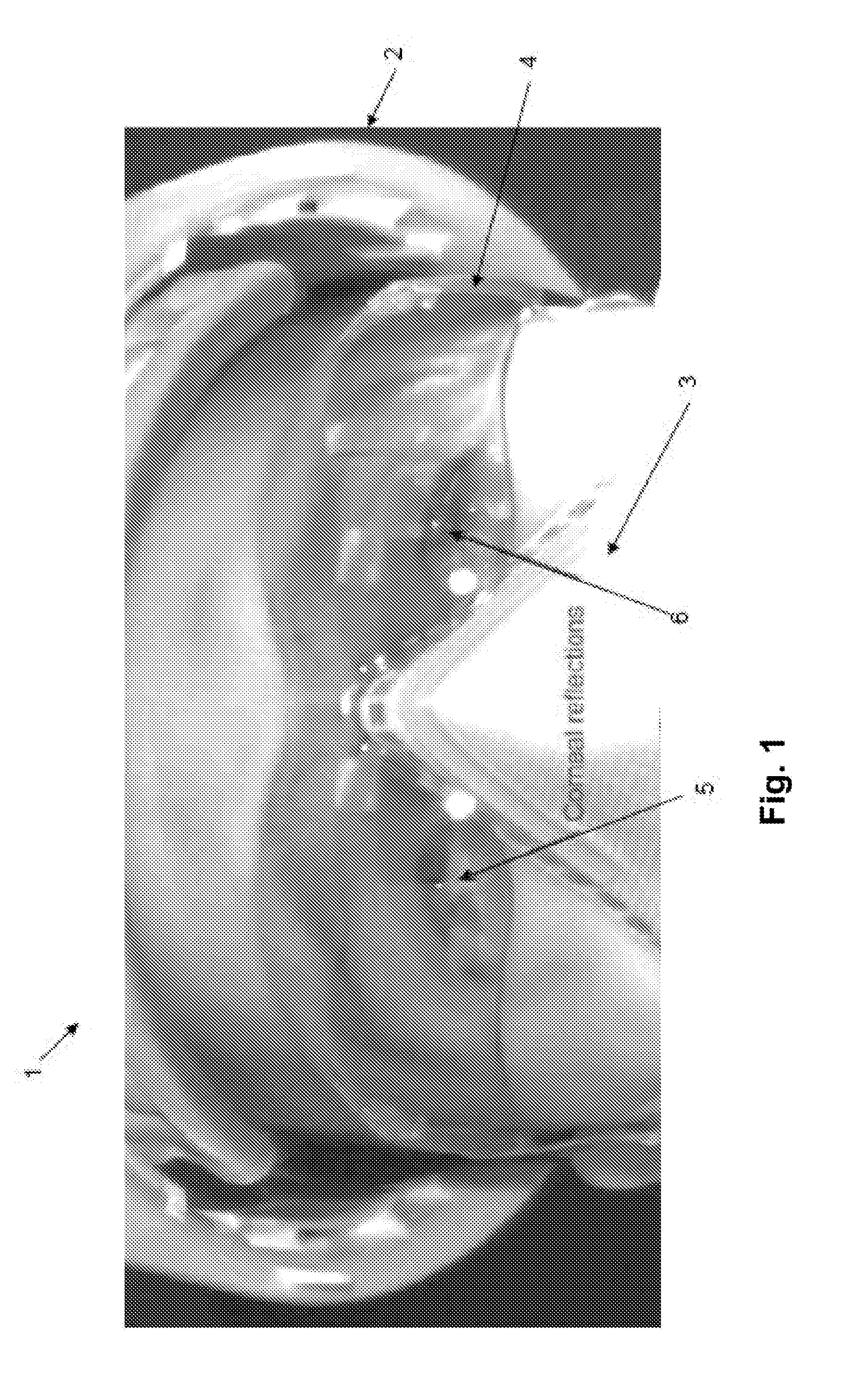
[0034]FIG. 1 illustrates an example noisy image 1 of a human head including hat 2, safety glasses 4 and air mask 3. From close examination of the image 1, it can be seen that two corneal reflections 5, 6 are also present in the image.

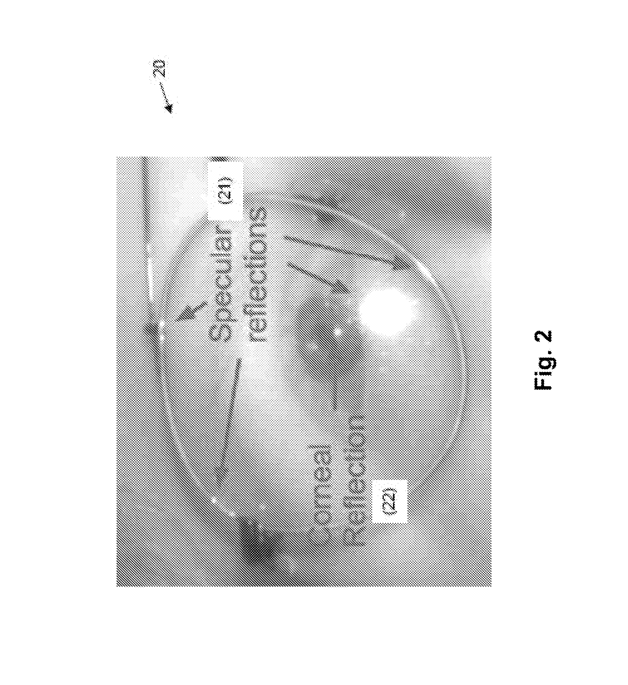
[0035]FIG. 2 illustrates a second example image of an imaging device recording a view of a single eye having glasses 20. In this example, the light source produces a number of specular reflections 21, in addition to a targeted corneal reflection 22.

[0036]In the preferred embodiment, the presence of corneal specular reflections is utilised to advantage. The preferred embodiment ...


PUM


Abstract

A method of determining the position of eyeballs within an image, the method including the steps of: (a) capturing a time series of image frames illuminated in a predetermined temporal manner by at least two spaced apart light sources, by at least one imaging sensor; (b) processing the image frames to determine specular reflection locations in the image frames; and (c) utilising the time series evolution of the location of the specular reflections to isolate corneal reflections from the determined specular reflection locations.

Description

FIELD OF THE INVENTION[0001]The present invention relates to the field of object detection and monitoring, and, in particular discloses a method and system for eye detection based on reflection structure. By way of example, embodiments of the invention are applicable in tracking the eye location of a user of a computer or mobile device (such as a smartphone or tablet), or a driver of a vehicle.BACKGROUND[0002]Any discussion of the background art throughout the specification should in no way be considered as an admission that such art is widely known or forms part of common general knowledge in the field.[0003]Proper detection of eyes in sensed noisy images can be difficult, especially in the presence of glasses with the occlusion generated by their frame and the reflections occurring on the lenses.[0004]Traditional computer vision algorithms for eye detection often rely on appearance (e.g. U.S. Pat. No. 7,020,337 to Viola and Jones entitled “System and method for detecting objects i...

Claims


Application Information

Patent Timeline
IPC IPC(8): G06K9/00G06T7/00G06T7/20G06F3/01
CPCG06K9/0061G06F3/013G06K9/00604G06T7/20G06T7/004G06V40/171G06V40/193G06V40/19
Inventor ROUGEAUX, SEBASTIAN
Owner SEEING MACHINES
Learn More