
Techniques for active passivation

a technology of active passivation and passivation ring, which is applied in the direction of optical radiation measurement, instruments, spectrometry/spectrophotometry/monochromators, etc., can solve the problems of difficult detection on timescales, affecting the response time of instruments, and affecting the detection accuracy of polar molecules, so as to prevent further binding of polar molecules

Active Publication Date: 2016-06-16
AERODYNE RES
View PDF2 Cites 10 Cited by
  • Summary
  • Abstract
  • Description
  • Claims
  • Application Information

AI Technical Summary

Benefits of technology

The patent describes a method for preventing sticky molecules from interacting with interfaces inside an infrared absorption spectrometer. This is achieved by applying a passivation species to the inlet of the instrument while a sample gas stream is being applied. The passivation species has a polar functional group that binds to the interfaces, creating a non-polar group to the gas phase to prevent further binding of polar molecules. This results in a protective coating that is continuously renewed during ongoing instrument use, ensuring its effectiveness. In addition, intermittent passivation is also employed, allowing for a period of rest while the built protective coating continues to prevent interaction of sticky molecules with the interfaces. Overall, this method provides a simple and effective way to prevent sticky molecules from causing damage to the instrument.

Problems solved by technology

However, the large dipoles and hydrophilic properties of these polar molecules render them difficult to detect on timescales less than approximately 1 minute.
However, the effects typically diminish over the course of instrument usage.
Thus, the response time of the instrument may gradually become slower, as an increasing fraction of the interfaces becomes coated in adsorptive matter.
However, recoating or cleaning or recoating generally involves discontinuing use of the instrument, bringing any internal vacuum to atmospheric pressure, and potentially disassembling significant portions of the instrument.
Considerable instrument downtime may be incurred.
However, such an approach may not successfully remove all water because of a) the possibly strong binding between water and the surface, which could be larger than the water-water interaction, and b) the presence of small crevices and pockets in all but the most pristine surfaces, which could be difficult to evacuate with heat.

Method used


Image

  • Techniques for active passivation
  • Techniques for active passivation
  • Techniques for active passivation

Examples


example results

[0038

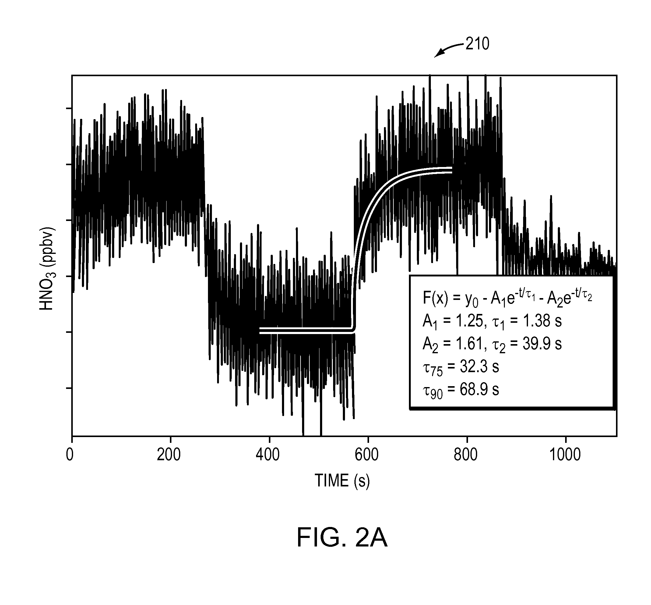
[0039]Application of a passivation species (either continuous or intermittent) may significantly improve response time of an output signal produced by a detector (e.g., MCT detector 118) to rapid changes in concentration. For example, in some cases, application of a passivation agent may decrease response time by more than a factor of 30 over operation without a passivation species.

[0040]FIG. 2A shows a graph 210 of typical HNO3 response time using the example instrument 100 of FIG. 1, absent a passivation agent. The rise and fall times of HNO3 may be best described by a double exponential in the form of F(x)=y0−A1e−t / τ1A2e−t / τ2, with τ1=1.38 s and τ2=39.9 s, and A1 / A2=0.78. The time required for the signal to achieve 75% and 90% of its final value after injection or removal of HNO3 may be 32.3 second (s) and 68.9 s, respectively (such that τ75=32.3 s and τ90=68.9 s). Thus, the example instrument 100, absent application of a passivation species may be capable of seeing HNO3 sig...


PUM


Abstract

In one embodiment, active (continuous or intermittent) passivation may be employed to prevent interaction of sticky molecules with interfaces inside of an instrument (e.g., an infrared absorption spectrometer) and thereby improve response time. A passivation species may be continuously or intermittently applied to an inlet of the instrument while a sample gas stream is being applied. The passivation species may have a highly polar functional group that strongly binds to either water or polar groups of the interfaces, and once bound presents a non-polar group to the gas phase in order to prevent further binding of polar molecules. The instrument may be actively used to detect the sticky molecules while the passivation species is being applied.

Description

BACKGROUND[0001]1. Technical Field[0002]The present disclosure relates generally to measurement of sticky molecules, and more specifically to techniques for preventing interaction of sticky molecules with interfaces inside of an instrument.[0003]2. Background Information[0004]Measurement of Nitric acid (HNO3), ammonia (NH3) and other polar molecules has proven increasingly important in the understanding of atmospheric processes. Their large dipole moments and hydrophilic properties are primary factors in their nucleation and condensation roles in atmospheric aerosol formation. For example, nitric acid is an important photochemical product during NOx oxidation and is an important test of our understanding of modeled photoreactivity in the atmosphere. However, the large dipoles and hydrophilic properties of these polar molecules render them difficult to detect on timescales less than approximately 1 minute. These polar molecules may not only be is “sticky” upon interfaces (i.e. surfac...

Claims


Application Information

Patent Timeline
IPC IPC(8): G01N33/00G01J3/10
CPCG01N33/006G01J3/108G01J2003/102G01N33/0054G01N33/0037G01J3/0297G01J3/42G01N33/0062Y02A50/20G01N27/4145G01N27/4141C12M41/32B01J2219/02B01J19/002
Inventor ROSCIOLI, JOSEPH R.HERNDON, SCOTT C.NELSON, JR., DAVID D.
Owner AERODYNE RES
Learn More