Coupling structure of sheath structure and coupling method thereof

Active Publication Date: 2016-06-09
NORITAKE KENSUKE +1
View PDF5 Cites 6 Cited by
  • Summary
  • Abstract
  • Description
  • Claims
  • Application Information

AI Technical Summary

Benefits of technology

The present invention allows for the flexible and cost-effective connection of metal wires through a connector. This leads to better electrical performance and prevents weak spots in the connection. The method also allows for efficient joining of wires and insulation compression. Additionally, a spacer is used to create a uniform gaps between the connector and the heat-resisting insulation, ensuring uniform compression during the manufacturing process.

Problems solved by technology

However, for example, in the case where the coupling structure is used as being arranged in piping, under the ground, or in a structure extending over the distance as great as several thousand meters or more, or in the case where a fluid whose flow velocity or viscosity is very great or a solid with great vibration is subjected to heating or temperature measurement, a great force such as tension, compression, twist, or shock continuously occurs at the coupling portion.
In particular, durability of the welded portions between the coupling sleeve opposite end portions and the metal sheath outer circumferential surface may be impaired.

Method used


Image

  • Coupling structure of sheath structure and coupling method thereof
  • Coupling structure of sheath structure and coupling method thereof
  • Coupling structure of sheath structure and coupling method thereof

Examples


first embodiment

[0074]Firstly, with reference to FIGS. 1 to 4, a description will be given of the present invention.

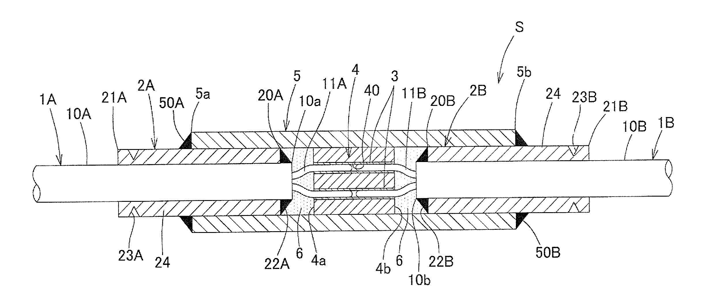
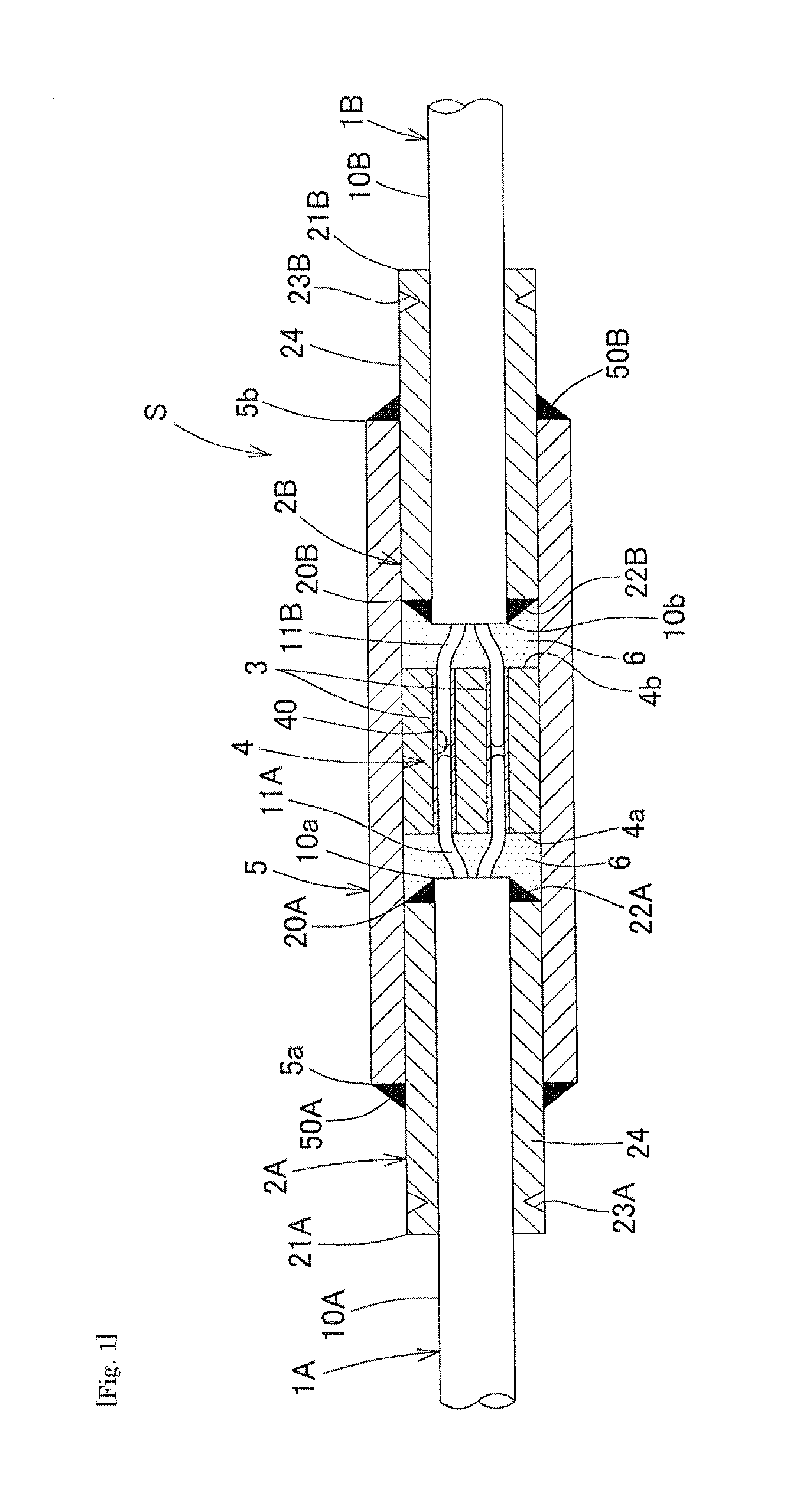
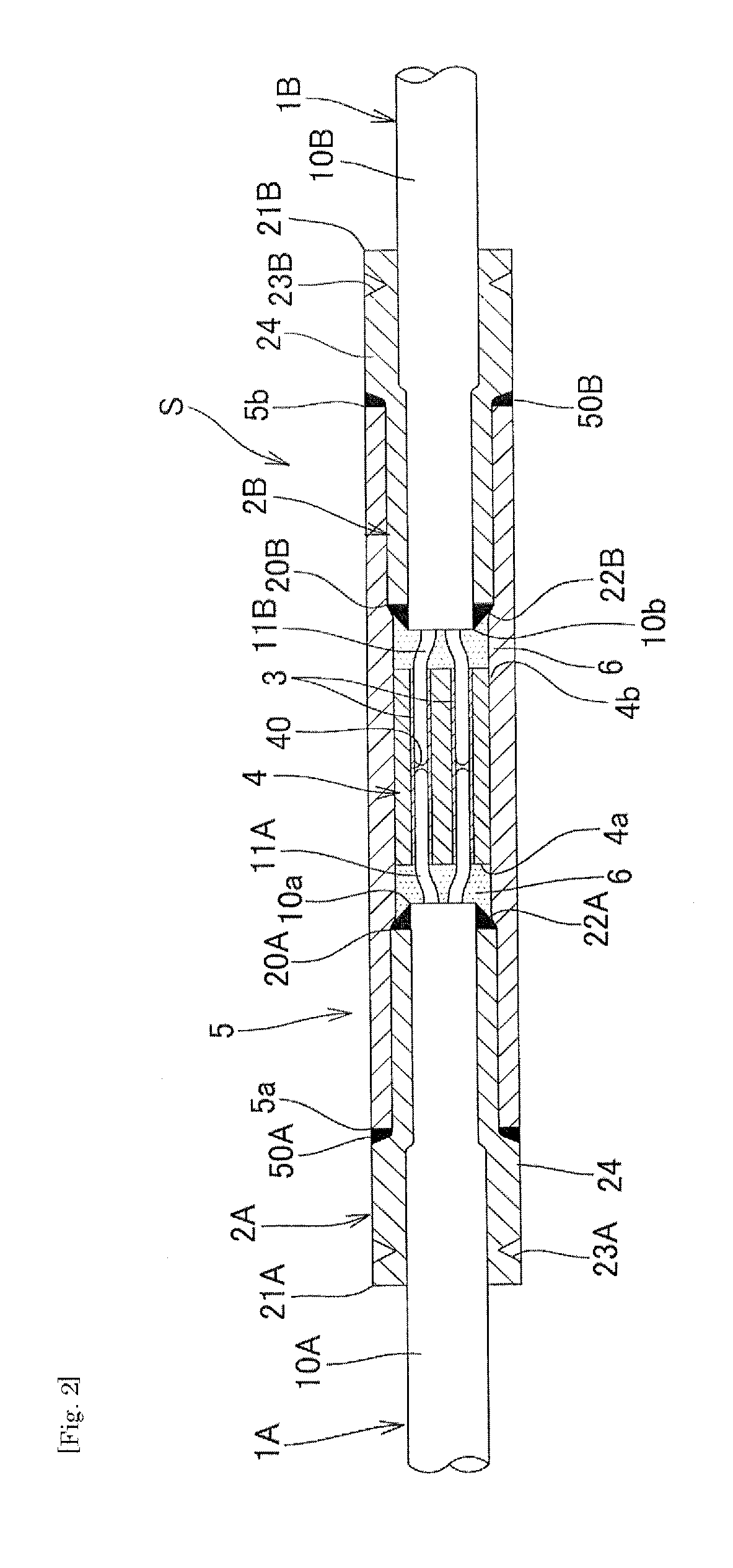
[0075]As shown in FIG. 1, a sheath structure assembly coupling structure S according to the present embodiment is structured such that a first sheath structure assembly 1A and a second sheath structure assembly 1B are coupled to each other at their respective end portions in the axial direction. The first sheath structure assembly 1A has at least one heater-use and / or temperature measuring sensor use metal wire 11A stored in a metal sheath 10A and has a heat resistant insulator packed in a gap. Similarly, the second sheath structure assembly 1B has at least one heater-use and / or temperature measuring sensor-use metal wire 11B stored in a metal sheath 10B and has a heat resistant insulator packed in a gap.

[0076]Specifically, the coupling structure S includes: at least one connector made of metal 3, the metal wire 11A projecting from the end portion of the metal sheath 10A of the first ...


PUM


Abstract

To provide a sheath structure assembly coupling structure and a sheath structure assembly coupling method, with which excellent workability and a reduction in costs can be achieved; a reduction in the strength of the connection portion or in the electrical connection can be prevented and a uniform and excellent electrical connection, can be achieved; with which excellent durability is maintained for a long period even in the usage environment in which a great force such a tension or the like continuously acts; and with which break or a reduction in insulating performance can be avoided.

Description

BACKGROUND OF THE INVENTION[0001]1. Field of the Invention[0002]The present invention relates to a sheath type heater or a sheath type temperature measuring sensor for performing heating or temperature measurement of fluid, solid and the like in various situations such as in piping, under the ground, or with a vacuum device. More specifically, the present invention relates to a coupling structure and a coupling method of a sheath structure assembly for coupling a plurality of sheath type heaters or sheath type temperature measuring sensors to one another in the axial direction, so as to extend the length.[0003]2. Description of the Background Art[0004]As the coupling structure of this kind, for example, the following coupling structure is proposed. A sheath type heater coupling structure includes: a tubular metal connector into which a heating wire projecting from a metal sheath end on the heating side and a non-heating wire projecting from a metal sheath end on the non-heating side...

Claims


Application Information

Patent Timeline
IPC IPC(8): H05B3/44H01R43/02H01R43/20H05B3/06
CPCH05B3/44H01R43/20H01R43/02H05B3/06H05B3/04H05B3/56G01K1/08
Inventor NORITAKE, KENSUKEHIRANO, KOZO
Owner NORITAKE KENSUKE
Why Eureka
Try Eureka