Nano-fiber spinning apparatus using centrifugal force and method of manufacturing nano-fiber using the same

a technology of nanofiber and centrifugal force, which is applied in the direction of centrifuges, filament/thread forming, manufacturing tools, etc., can solve the problems of reducing productivity, reducing the discharge rate per unit hole of the nozzle per hour, so as to avoid the danger of working, easy volatilization and recovery of solvents, and high productivity

Inactive Publication Date: 2016-05-26
WOORI NANO +1
View PDF7 Cites 3 Cited by
  • Summary
  • Abstract
  • Description
  • Claims
  • Application Information

AI Technical Summary

Benefits of technology

[0019]The present invention may only use centrifugal force and air flow without application of electrostatic power, and spin nano-fibers without using conventional spinning nozzle, therefore, can attain some advantages of, in particular: avoiding danger in working due to application of high voltages; preparing nano-fibers with high productivity (discharge rate); overcoming troubles in nozzle replacement and cleaning thereof; easily volatilizing and recovering a solvent; and efficiently preventing a phenomenon of dripping a spinning dope in a liquid state (‘drop generation phenomenon’) on the collector other than a fiber form, thereby improving quality of nano-fiber webs.

Problems solved by technology

However, since the conventional electro-spinning apparatuses as described above electrically spin (discharge) the spinning dope through the fixed nozzle, electro-spinning has been executed by electrostatic power alone and thus a discharge rate per unit hole of the nozzle per unit hour was very low in a level of 0.01 g to decrease productivity.
Consequently, problems such as difficulties in mass production, highly complex and complicate replacement and cleaning of nozzles, or the like, have been entailed.
However, although the above electro-spinning apparatus may utilize centrifugal force and electrostatic power to improve the production rate per unit hour even without any nozzle, it entailed such problems that the spinning dope is continuously fed into a conical vessel to cause a difficulty in continuous production, a collector is located below the conical vessel to occur a phenomenon of dripping the spinning dope in a liquid state (‘drop generation phenomenon’) other than a fiber form, and the like.
The above-described electro-spinning system mode embraces very low production rate of nano-fibers per unit hole and using nozzles to cause a problem of troublesome cleaning.
However, the above-described conventional methods cannot collect nano-fibers upwardly to hence have a difficulty in production of a nano-fiber web, and encounter a problem of deteriorated solvent volatility.

Method used


Image

  • Nano-fiber spinning apparatus using centrifugal force and method of manufacturing nano-fiber using the same
  • Nano-fiber spinning apparatus using centrifugal force and method of manufacturing nano-fiber using the same
  • Nano-fiber spinning apparatus using centrifugal force and method of manufacturing nano-fiber using the same

Examples


example 1

[0042]Polyvinylalcohol having a weight average molecular weight Mw of 80,000 was dissolved in water as a solvent to prepare a spinning dope with a solid content of 30 wt. % and a viscosity of 8,500 cps.

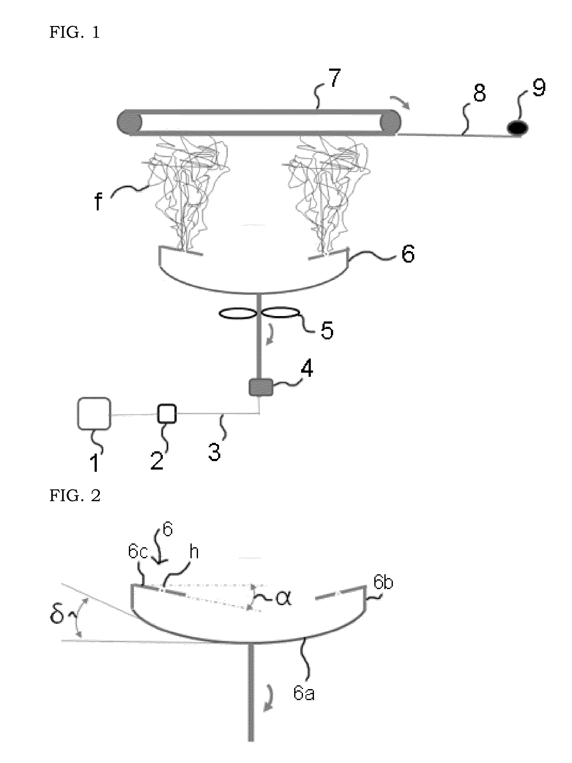
[0043]Next, as illustrated in FIG. 1, the prepared spinning dope was fed into a nano-fiber spinning apparatus 6 at a feeding rate of 2 cc / min per each metering pump, wherein the apparatus 6 includes: (i) a top plate 6c which has nano-fiber spinning holes h, and is slantly formed at an inclination angle α decreasing from outer peripheral edges to a center with respect to a virtual horizontal line connecting the outer peripheral edges of a cylindrical side wall 6b so as to have a disk shape; (ii) a bottom plate 6a having a curved surface which is concaved and inclined upwardly so as to have a dish shape; and (iii) the cylindrical side wall 6b which connects the top plate 6c and the bottom plate 6a, so that the apparatus 6 has a spin-top form in overall viewpoint. Then, centrifugal force...

example 2

[0049]Polyvinylalcohol having a weight average molecular weight Mw of 80,000 was dissolved in water as a solvent, to prepare a spinning dope with a solid content of 25 wt. % and a viscosity of 7,000 cps.

[0050]Next, as illustrated in FIG. 1, the prepared spinning dope was fed into a nano-fiber spinning apparatus 6 at a feeding rate of 2 cc / min per each metering pump, wherein the apparatus 6 includes: (i) a top plate 6c which has nano-fiber spinning holes h, and is slantly formed at an inclination angle decreasing from outer peripheral edges to a center with respect to a virtual horizontal line connecting the outer peripheral edges of a cylindrical side wall 6b so as to have a disk shape; (ii) a bottom plate 6a having a curved surface which is concaved and inclined upwardly so as to have a dish shape; and (iii) the cylindrical side wall 6b which connects the top plate 6c and the bottom plate 6a, so that the apparatus 6 has a spin-top form in overall viewpoint. Then, centrifugal force ...


PUM

PropertyMeasurementUnit
inclination angleaaaaaaaaaa
speedaaaaaaaaaa

Abstract

Disclosed is a nano-fiber spinning apparatus using centrifugal force which includes: (i) a top plate 6c which has nano-fiber spinning holes h, and is slantly formed at an inclination angle α with a virtual horizontal line connecting top of a side wall 6b in a disk shape; (ii) a bottom plate 6a having a curved surface which is concaved and inclined upwardly in a dish shape; and (iii) the cylindrical side wall 6b connecting the top plate 6c and the bottom plate 6a, so as to be wholly formed in a spin-top shape. Also, disclosed is a method of manufacturing nano-fibers which includes, after supplying a spinning dope to the above nano-fiber spinning apparatus 6, spinning nano-fibers with centrifugal force toward a collector 7 provided above the apparatus while generating an air flow toward the collector by an air generator provided below the nano-fiber spinning apparatus 6.

Description

RELATED APPLICATIONS[0001]This application claims priority to Korean Patent Application No. 10-2014-0162364, filed on Nov. 20, 2014 in the Korean Intellectual Property Office, the entire disclosure of which is incorporated herein by reference.BACKGROUND OF THE INVENTION[0002]1. Field of the Invention[0003]The present invention relates to a nano-fiber spinning apparatus using centrifugal force and a method of manufacturing nano-fibers using the same, and more specifically, to a method of manufacturing nano-fibers only using centrifugal force and air flow, which can achieve high production per unit hour without occurrence of a phenomenon that a spinning dope drips in a liquid state (hereinafter referred to as a “drop generation phenomenon”) even though electrostatic power is not applied, as well as a nano-fiber spinning apparatus used for the above method.[0004]2. Description of the Related Art[0005]In general, nano-fibers have been prepared by using an electronic spinning (‘electro-s...

Claims


Application Information

Patent Timeline
Patent Type & Authority Applications(United States)
IPC IPC(8): D01D5/18B04B5/00
CPCB04B5/00D01D5/18
Inventor KIM, HAK-YONGHAN, TAE-HWANKIM, TAE-WOOLIM, BAEK-HOAN, TAE-HEEKIM, JONG-WANCHAE, SU-HYEONG
Owner WOORI NANO
Why Eureka
Try Eureka