Optical scanner and scanned lens optical probe
a technology which is applied in the field of optical scanner and optical probe, can solve the problems of dimmer objects, low signal to noise ratio, and optical systems optimized for on-axis imaging that are not simultaneously optimized for off-axis imaging, and achieves the effect of reducing or eliminating lateral chromatic shift and high speed
- Summary
- Abstract
- Description
- Claims
- Application Information
AI Technical Summary
Benefits of technology
Problems solved by technology
Method used
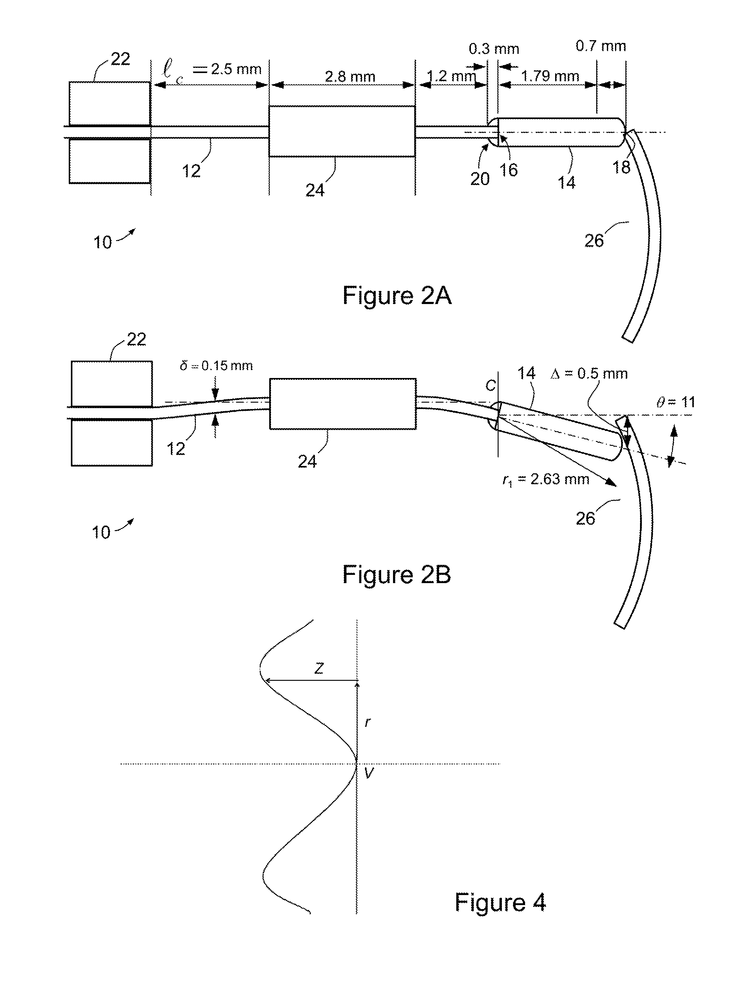
Image


Examples
example 1
Chromatically Uncorrected 0.26 NA System “Uncorrected 0.40 / 0.26 NA”
[0123]FIG. 6 is a schematic view of a lens group 60 suitable for use in a scanner such as optical system 10, shown with a window or coverslip 68, a tissue specimen 69 and rays for a 0.095 NA input from a lightguide. This design assumes that the focus is 50 or 99 μm deep into specimen 69 (see “Nominal imaging depth” in Table 1). Lens group 60 constitutes an 0.26 NA uncorrected system, and is adapted for FITC (fluorescein isothiocyanate) one photon fluorescence confocal imaging with FITC as the fluorophore; hence, the driving wavelength is 488 nm and the fluorescence returns in a band stretching from roughly 520 nm to 550 nm with a 532 nm fluorescence peak wavelength. The optical performance is designed to be slightly better than that of a bulk optic system of the type shown in FIG. 1. Lens group 60 has a substrate 62 of Schott (trade mark) N-SF66 and the aspheric lens 64 of Ohara (trade mark) L-LAM60, which meet at a ...
example 2
Chromatically Uncorrected 0.30 NA System “Uncorrected 0.47 / 0.30NA”
[0124]FIG. 7 is a schematic view of a lens group 70, shown with a window or coverslip 78 and a tissue specimen 79. This example is also suitable for use in a scanner such as optical system 10, being adapted for FITC one photon fluorescence confocal imaging but with optical performance significantly better than that of the bulk optic system of FIG. 1. Its shorter length and higher magnification makes it slightly more sensitive to manufacturing imperfections (discussed below). Lens group 70 comprises a substrate 72 of Ohara S-NPH2 and an aspheric lens 74 of Schott L-LAM60; substrate 72 of Ohara S-NPH2 yields slightly better partial chromatic correction at the higher numerical aperture.
[0125]This numerical aperture is approximately the highest that is worth striving for with an uncorrected system of this sort, because the axial responses (i.e. the maximum intensity of the focussing light in a given plane of constant axia...
example 3
Fully Chromatically Corrected 0.33 NA System “Universal 0.50 / 0.33NA”
[0127]FIG. 8 is a schematic view of a lens group 80, shown with a window or coverslip 88 and a tissue specimen 89. This example is also suitable for use in a scanner such as optical system 10, and comprises a substrate 82 of Ohara S-NPH2 and an aspheric lens 84 Ohara L-LAM60, which meet at a spherical interface 86. Lens group 80 is adapted to transmit light at wavelengths between 450 nm and 850 nm to essentially the same focus, to within a micron, owing to the opposite wavelength variations for the optical powers from spherical interface 86 on the one hand and the aspherical interface 87 between the Ohara L-LAM60 glass of aspheric lens 84 and freespace at the distal tip of lens group 80.
[0128]As a result, lens group 80 can be used for a variety of many-channel one-photon or two photon fluorescence / reflection confocal microscopy or endoscopy systems. Arbitrarily many drive wavelengths in the band 450 nm to 850 nm can...
PUM
| Property | Measurement | Unit |
|---|---|---|
| fluorescence wavelength | aaaaa | aaaaa |
| wavelength | aaaaa | aaaaa |
| frequency | aaaaa | aaaaa |
Abstract
Description
Claims
Application Information
 - R&D
- Intellectual Property
- Life Sciences
- Materials
- Tech Scout
- Unparalleled Data Quality
- Higher Quality Content
- 60% Fewer Hallucinations
Browse by: Latest US Patents, China's latest patents, Technical Efficacy Thesaurus, Application Domain, Technology Topic, Popular Technical Reports.
© 2025 PatSnap. All rights reserved.Legal|Privacy policy|Modern Slavery Act Transparency Statement|Sitemap|About US| Contact US: help@patsnap.com