
Isolatable Non-Slam Piston Check Valve

Active Publication Date: 2016-05-19
SAUDI ARABIAN OIL CO
View PDF7 Cites 7 Cited by
  • Summary
  • Abstract
  • Description
  • Claims
  • Application Information

AI Technical Summary

Benefits of technology

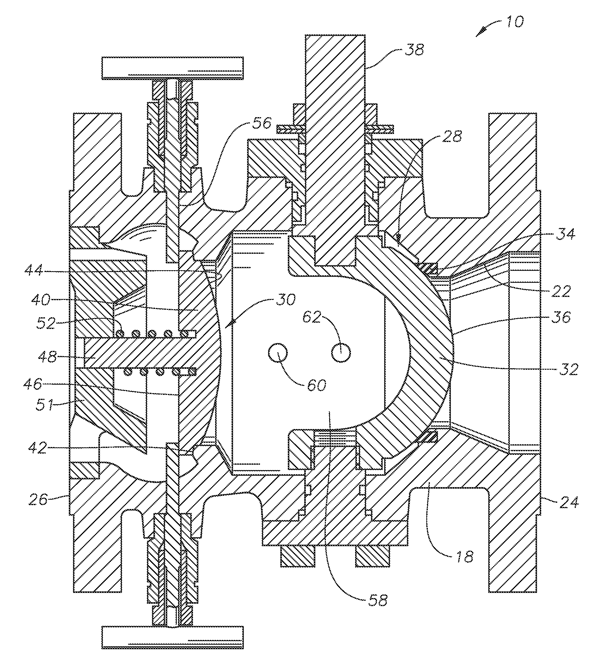
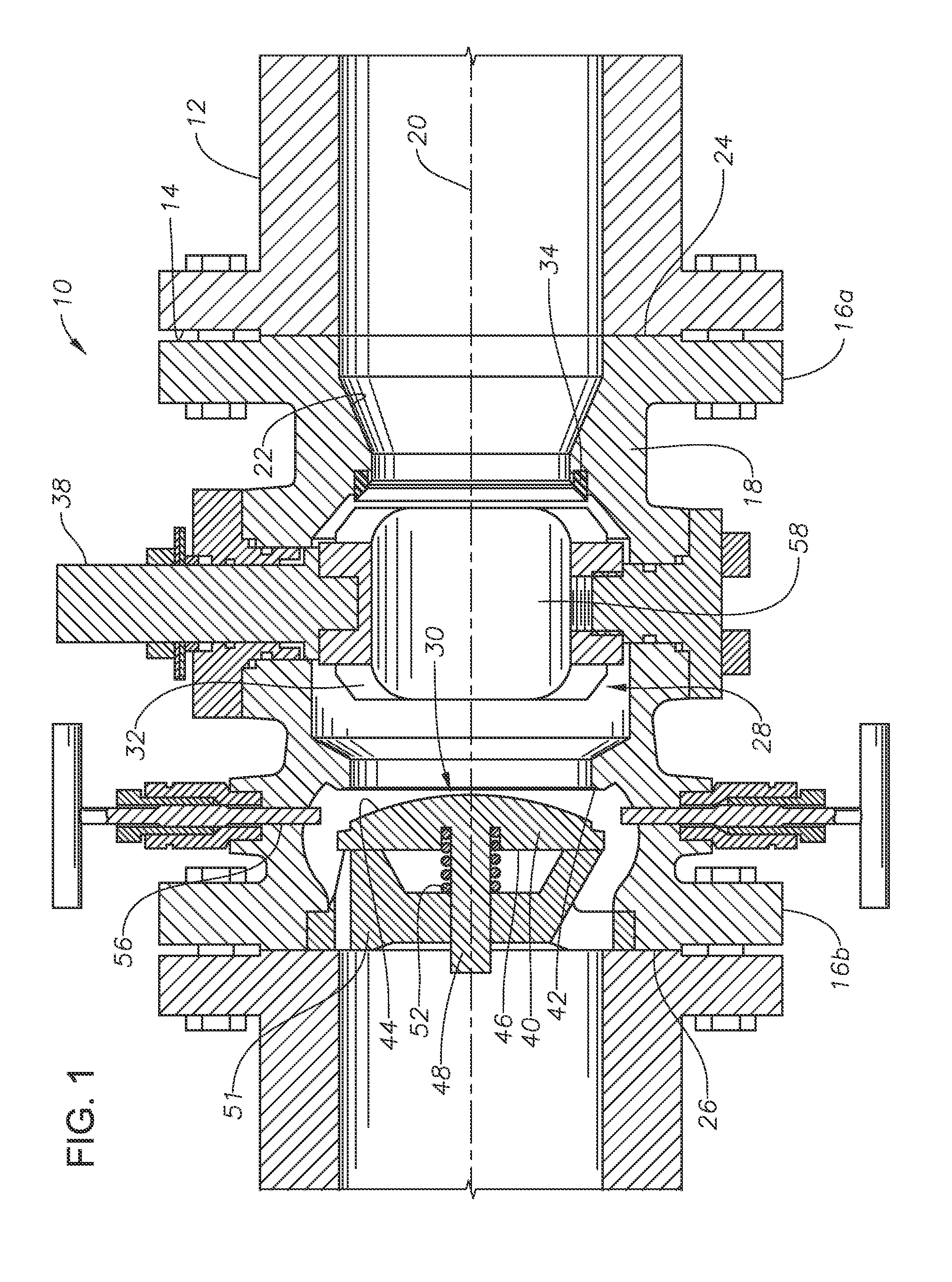
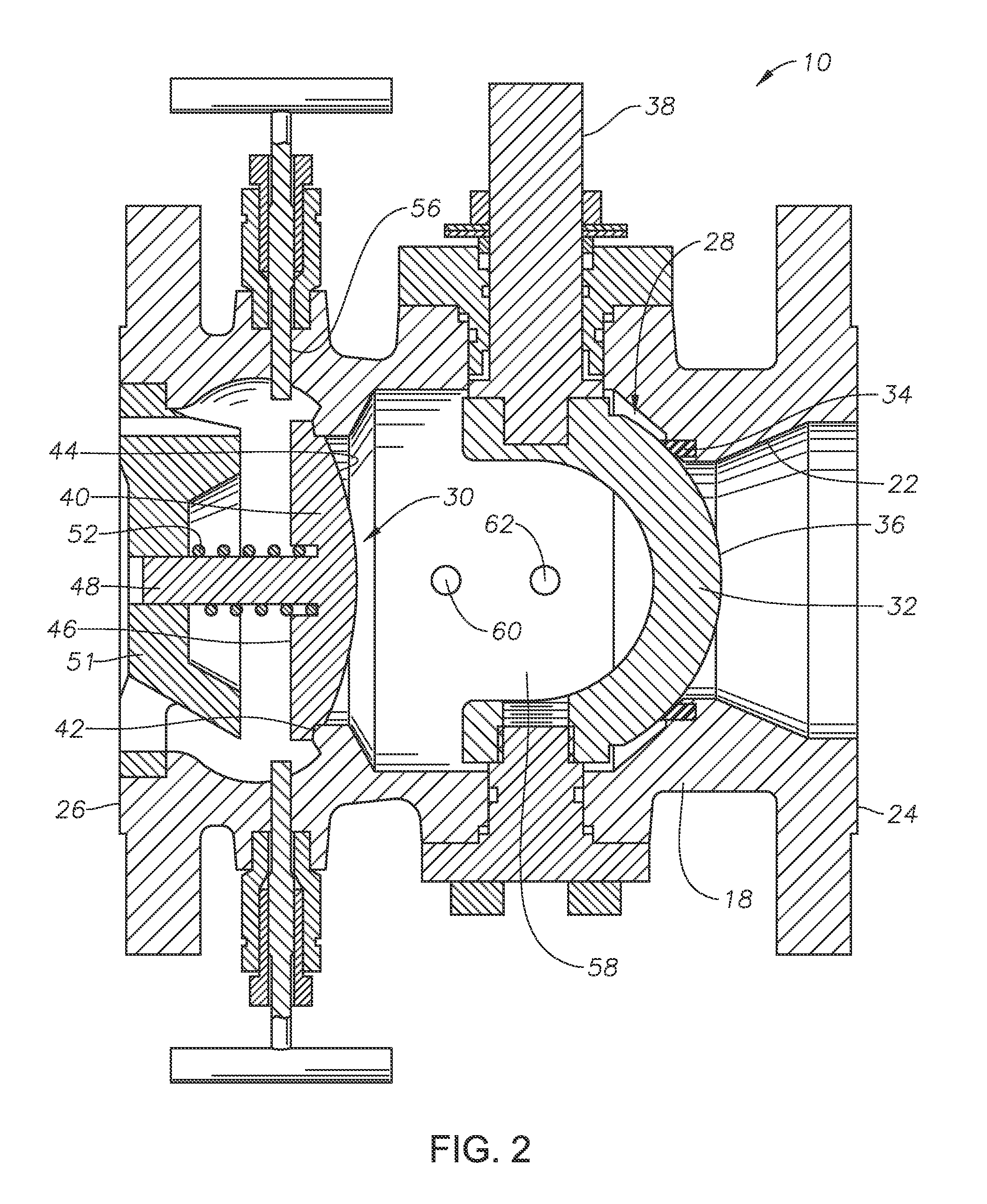
The present patent provides a valve assembly that can accommodate both a check valve and a block valve using a single standard length body. This eliminates the need for separate valves and reduces weight, space, and cost in congested systems. The valve assembly includes a segment ball valve and a check valve piston, which can be locked in position to prevent fluid from reaching the check valve. The valve assembly can be used in double block and bleed operations for on-stream hydrocarbon segregation. The patent also provides a locking mechanism for securely closing the check valve and a vent for selectively venting the fluid located in the cavity. The valve assembly can be connected between flanges of a standardized piping system. The technical effects of this patent include reducing the number of valve connections, reducing weight and space requirements, and achieving cost savings.

Problems solved by technology

Therefore the spacing allowed for the valve cannot be easily adjusted to allow for a larger valve assembly to be connected between the flanges of the piping system.

Method used


Image

  • Isolatable Non-Slam Piston Check Valve
  • Isolatable Non-Slam Piston Check Valve
  • Isolatable Non-Slam Piston Check Valve

Examples


Embodiment Construction

[0021]The present invention will now be described more fully hereinafter with reference to the accompanying drawings which illustrate embodiments of the invention. This invention may, however, be embodied in many different forms and should not be construed as limited to the illustrated embodiments set forth herein. Rather, these embodiments are provided so that this disclosure will be thorough and complete, and will fully convey the scope of the invention to those skilled in the art. Like numbers refer to like elements throughout, and the prime notation, if used, indicates similar elements in alternative embodiments or positions.

[0022]In the following discussion, numerous specific details are set forth to provide a thorough understanding of the present invention. However, it will be obvious to those skilled in the art that the present invention can be practiced without such specific details. Additionally, for the most part, details concerning well drilling, reservoir testing, well c...


PUM


Abstract

A valve assembly includes a valve body with a central passage, an upstream end for receiving a fluid, and a downstream end for discharging the fluid. A segment ball valve rotates between a valve open position to allow the fluid to flow through the central passage, and a valve closed position to prevent the fluid from flowing through the central passage. A check valve located within the central passage downstream from the segment ball valve is biased to prevent the fluid from traveling upstream through the central passage, and to allow the fluid to travel downstream past the check valve. A locking mechanism secures the check valve in a locked position to prevent the fluid from flowing past the check valve. A sealable cavity is located between the segment ball valve and the check valve, to contain a neutral media to achieve a double block and bleed feature.

Description

BACKGROUND OF THE INVENTION[0001]1. Field of the Invention[0002]The present invention relates generally to valves, and in particular to industrial check and block valves.[0003]2. Description of the Related Art[0004]In industrial operations with piping systems, such as hydrocarbon refineries, petrochemical plants, and onshore or offshore hydrocarbon production projects, a standardized piping system can have a set face to face dimension provided for each valve that restricts the valve space within the piping system to assure standardization and interchangeability with any type of valve from different manufacturers for a given pressure system. This spacing standardization is applicable to both block valves, which can open and close to turn a fluid flow on and off, and check valves, which are non-return flow valves.[0005]In such application, the piping systems are often provided with flanges for attachment to the valves. Therefore the spacing allowed for the valve cannot be easily adjus...

Claims


Application Information

Patent Timeline
IPC IPC(8): F16K5/10F16K35/04F16K15/02
CPCF16K5/10F16K35/04F16K15/02F16K15/18F16K27/067F16K15/1848
Inventor AL-AMRI, OMAR M.
Owner SAUDI ARABIAN OIL CO
Learn More