Rotating Machine
a rotating machine and rotating shaft technology, applied in the direction of current collectors, dynamo-electric components, cooling/ventilation arrangements, etc., can solve the problems of increased mechanical loss, increased electrical loss and vibration of brushes, and less loss, and achieve good contact state
- Summary
- Abstract
- Description
- Claims
- Application Information
AI Technical Summary
Benefits of technology
Problems solved by technology
Method used
Image
Examples
first embodiment
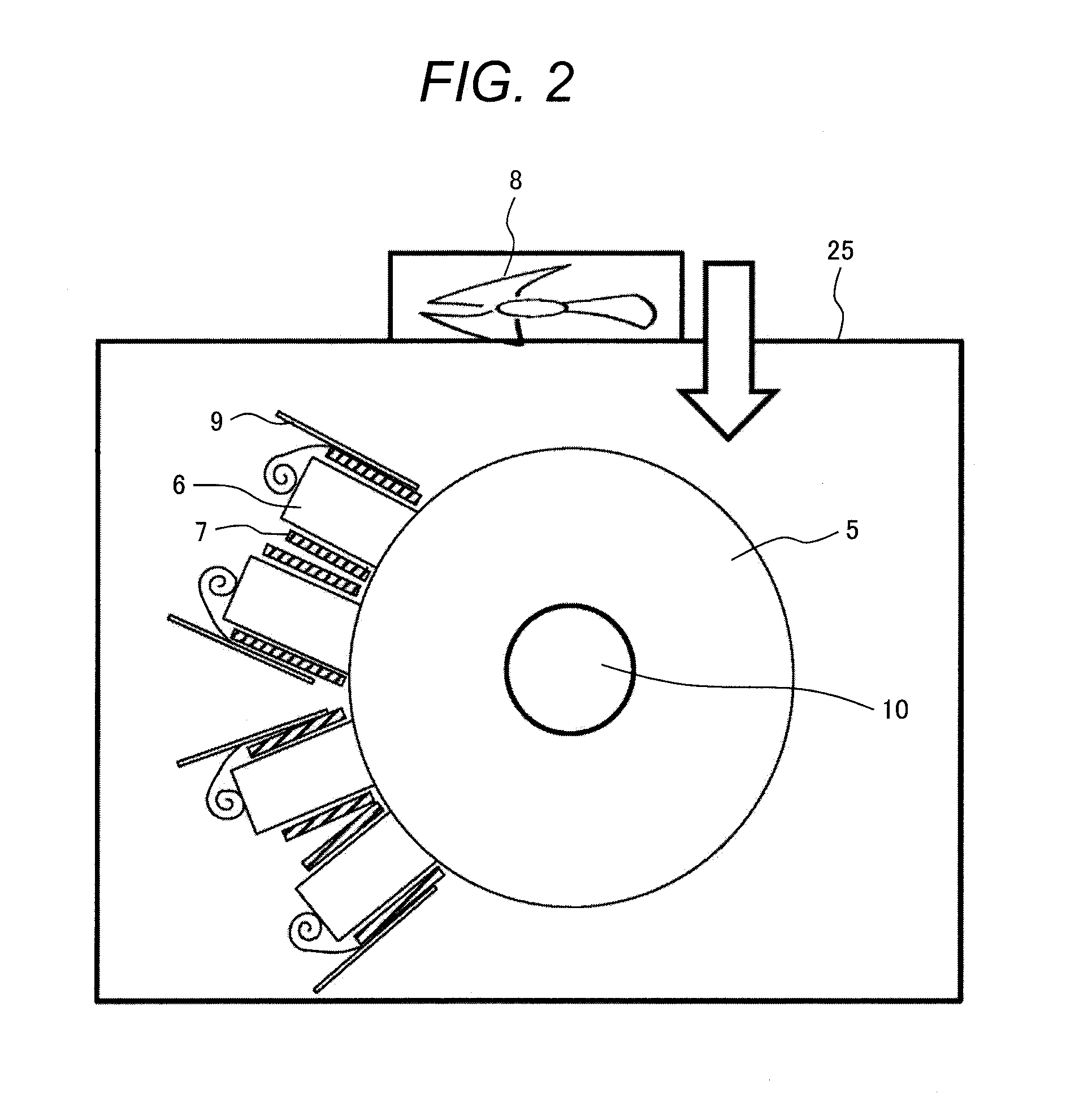
[0027]A first embodiment of the rotating machine with brush according to the present invention will be described in detail referring to FIG. 4. This embodiment shows an exemplary use of the spiral spring and the shape-memory alloy spring for constituting the pressing mechanism. FIG. 4 is a view representing an exemplary structure of the brush 6, the brush holder 7, and the pressing mechanism 9 according to the embodiment. In the embodiment, referring to FIG. 4, a spiral spring 91 and a shape-memory alloy spring 92 are combined to constitute the pressing mechanism 9 for increasing the pressure applied to the brush 6 upon the contact failure. In this embodiment, the brush 6 is connected to the brush holder 7 using the shape-memory alloy spring 92 and the spiral spring 91. The spiral spring 91 is fixed to the side surface of the brush holder 7. In the stable contact state, the pressure does not vary with wear of the brush 6 as the constant load spring is used. The spiral spring 91 is d...
second embodiment
[0031]A second embodiment of the rotating machine with brush according to the present invention will be described in detail referring to FIG. 5. This embodiment is configured to use a shape-memory alloy spring 93 (especially, the coil spring is used in this example) as a spring for pressing the brush 6 against the slipring 5. In the embodiment, a brush pressing plate 11 is disposed between the shape-memory alloy spring 93 and the brush and the brush pressing plate 11 presses the brush 6 so that the brush 6 approaches the slipring 5. According to the embodiment of the structure including the shape-memory alloy coil spring 93 and the brush 6, the coil spring 93 is disposed between the brush pressing plate 11 and the brush holder 7 to connect the brush holder 7 at the side closer to the slipring 5 and the brush pressing plate 11.
[0032]In this embodiment, good contact state between the brush 6 and the slipring 5 may be recovered from the contact failure by detecting the temperature rise...
third embodiment
[0033]A third embodiment of the rotating machine with brush according to the present invention will be described in detail referring to FIG. 6. This embodiment is configured to use a shape-memory alloy spiral spring 94 as a spring for pressing the brush 6 against the slipring 5. The structure of this embodiment uses the shape-memory alloy spiral spring in place of the spiral spring for the pressing mechanism 9 shown in FIG. 2. The shape-memory alloy spring 94 of this embodiment directly connects the brush 6 and the brush holder 7.
[0034]In this embodiment, good contact state between the brush 6 and the slipring 5 may be recovered from the contact failure by detecting the temperature rise with the shape-memory alloy spiral spring 94 and by increasing the pressure applied to the brush 6. This makes it possible to prevent abnormal wear and burnout of the brush 6 and the slipring 5 with simple structure advantageously. Furthermore, automatic application of the desired pressure (based on ...
PUM
 Abstract
Description
Claims
Application Information
 - R&D
- Intellectual Property
- Life Sciences
- Materials
- Tech Scout
- Unparalleled Data Quality
- Higher Quality Content
- 60% Fewer Hallucinations
Browse by: Latest US Patents, China's latest patents, Technical Efficacy Thesaurus, Application Domain, Technology Topic, Popular Technical Reports.
© 2025 PatSnap. All rights reserved.Legal|Privacy policy|Modern Slavery Act Transparency Statement|Sitemap|About US| Contact US: help@patsnap.com


