Eureka AIR delivers breakthrough ideas for toughest innovation challenges, trusted by R&D personnel around the world.

Virtual component alignment

a component and virtual technology, applied in the field of virtual component alignment, can solve the problems of missing, or ‘negative’, material, parts that would otherwise be scrapped, and the dimensional variation of the technique can exceed the drawing specifications of the component, so as to reduce the variability of the process, increase the dimensional capability at the operation, and reduce the rework at the operation.

Active Publication Date: 2016-04-21
ROLLS ROYCE PLC
View PDF6 Cites 8 Cited by
  • Summary
  • Abstract
  • Description
  • Claims
  • Application Information

AI Technical Summary

Benefits of technology

The invention is a method that aligns a digitized model of a component with a CAD model by adjusting the weighting of different regions of the model based on their location relative to the tolerances of the component. This allows the method to be sensitive to misalignment caused by missing or negative material, while being less sensitive to excess material in regions that could be subsequently machined. By prioritizing the repositioning of regions that exceed the tolerances and reducing the impact of operator influence, this method improves dimensional capability, reduces rework and scrap, and allows for greater dimensional control of the component. The invention also allows for data interrogation from data-rich metrology systems such as optical, laser, and computerized tomography.

Problems solved by technology

These casting techniques inherently produce levels of dimensional variation that can exceed drawing specifications for the components in question.
In particular, a part that shows missing, or ‘negative’, material when aligned using the defined datum points for that part would otherwise be scrapped because these voids cannot simply be filled.
This can be extremely difficult, especially for parts with complex core geometries or cooling passages where the wall thickness of the part can vary significantly from one location to another.
Removing material from one location risks moving one or more points outside the drawing tolerances, which would then necessitate an additional reworking operation subject to the same risks as outlined above.
It should be understood, therefore, that the manual operation described above is, by its nature, susceptible to high variation in effectiveness.
Even highly skilled operators can struggle due to the large number of interrelated parameters that must be considered and the limited visual feedback during the work.
This results in inconsistency of dimensional conformance of the parts within the tolerance bands.
This can then lead to decreased performance of the part when used in service.
Furthermore, if insufficient skill or care is used in the re-working process, a theoretically recoverable part will still need to be scrapped because, for example, removal of material from one datum point either moves other parts of the component too far from the drawing tolerances to be recoverable or reduces the wall thickness in an area below the minimum allowed.
Due to the risks associated with removing too much material or removing material from the wrong place, the reworking operation is typically iterative, with several small adjustments being made and the component being re-measured between each adjustment, making the manual inspection and processing inefficient and time consuming.
The manual processing / reworking described above can thus be seen to lead to unnecessary amounts of reworking, which in certain cases can still result in a component that must be scrapped.
The linishing belts and wheels typically used for the reworking also expose the operators to hand and arm vibration, so there are additional health and safety issues associated with the manual processing of the components.

Method used


Image

  • Virtual component alignment
  • Virtual component alignment
  • Virtual component alignment

Examples


Embodiment Construction

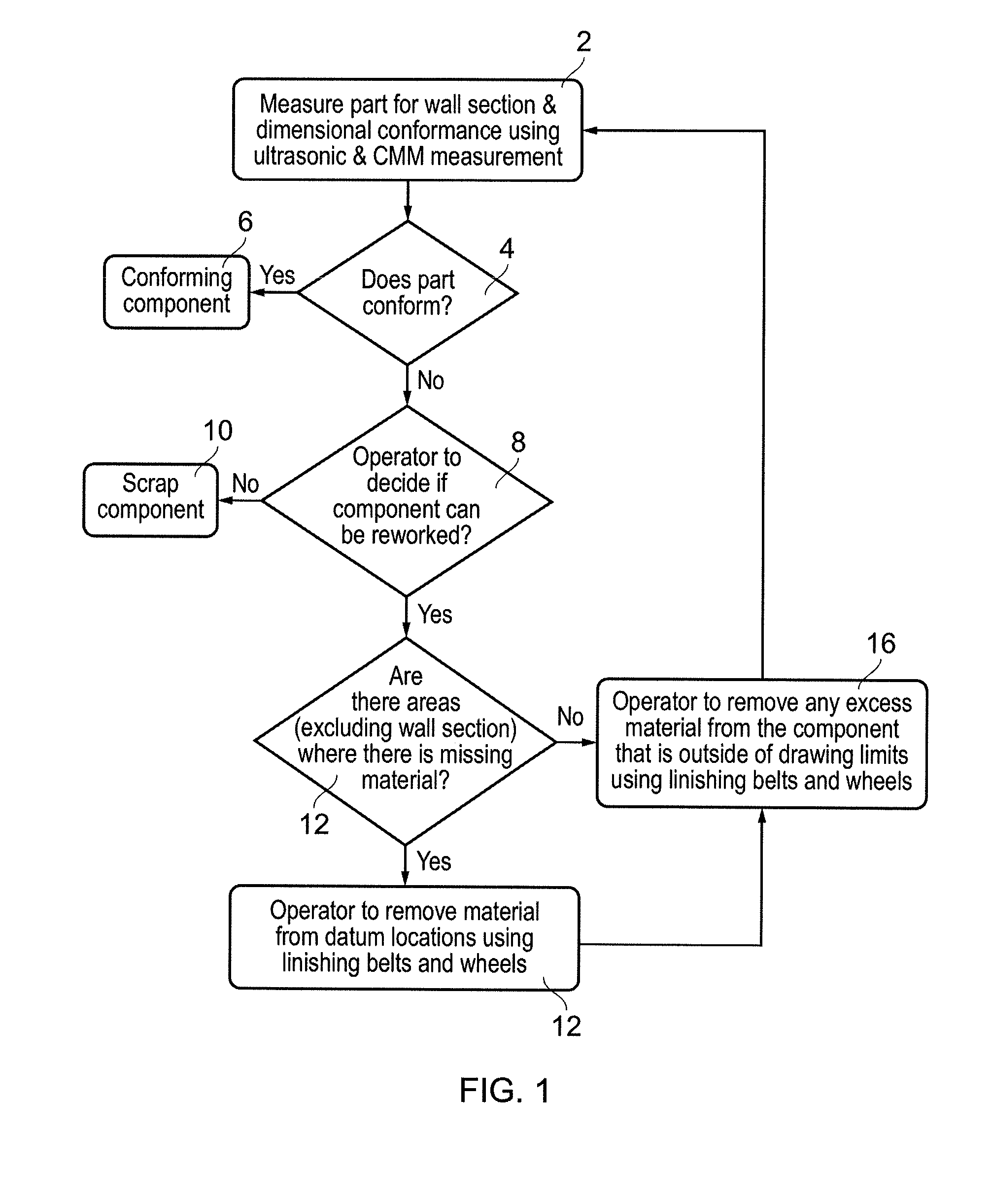
[0051]The current, manual, inspection and reworking process is illustrated in the process flow diagram of FIG. 1. Once a part has been carefully measured using, for example, ultrasonic and CMM measurement 2, it is checked for conformity with the drawings 4. If it is found to conform, then it is simply sent for finishing 6. If, on the other hand, the part is found not to conform with the drawings, then it is left to the operator to decide, using their experience, expertise and judgement, whether or not the part can be salvaged by reworking 8.

[0052]If, in the view of the operator, the component cannot be salvaged, then it is simply scrapped 10. If the operator is of the opinion that reworking of the component is possible, then they will proceed to carefully remove material from the component. If there are areas where material is ‘missing’, compared with the drawings 12, then the operator will first remove material specifically from the datum locations 14, and then more generally from ...


PUM


Abstract

This invention concerns improvements in the inspection, assessment and re-working of manufactured components such as nozzle guide vanes (NGVs) and blades, in particular by improving the comparison of the component with nominal data. Dimensional data of a physical component is obtained and used to create a virtual digitised model of the component which is aligned with a nominal CAD model of the component in a virtual space. The correspondence is assessed and used to adjust weightings of different regions of the digitised model to improve the alignment. This process is repeated within the digital space until either conformance is reached or it is determined that this is not possible.

Description

BACKGROUND OF THE INVENTION[0001]The present invention relates to improvements in the inspection, assessment and re-working of manufactured components to improve uniformity, reduce the level of physical reworking of the parts and reduce the number of scrap parts. In particular, the invention relates to a virtual alignment system and method for components such as nozzle guide vanes (NGVs) and blades from a gas turbine.[0002]Components such as nozzle guide vanes (NGVs) and blades are often created using precision casting techniques. In particular, investment casting techniques are often used, particularly where complex internal cooling geometry has to be formed within the component. These casting techniques inherently produce levels of dimensional variation that can exceed drawing specifications for the components in question. In order to rectify the dimensional variations from the casting process, as well as to improve the surface finish and bring the parts back into dimensional conf...

Claims


Application Information

Patent Timeline
Patent Type & Authority Applications(United States)
IPC IPC(8): G05B19/4099
CPCG05B19/4099G05B2219/32228G05B2219/35134G05B19/4207G05B2219/35128G05B2219/37205G05B2219/45147F05D2230/18G01B9/08G01B11/03G05B19/401G05B19/4097G05B2219/37617G06F30/00
Inventor ADDICOTT, PAUL DAVID
Owner ROLLS ROYCE PLC
Why Eureka
Eureka Blog
Learn More