Temperature compensated plate resonator

Active Publication Date: 2016-04-07
TEKNOLOGIAN TUTKIMUSKESKUS VTT OY
View PDF6 Cites 28 Cited by
  • Summary
  • Abstract
  • Description
  • Claims
  • Application Information

AI Technical Summary

Benefits of technology

The invention provides a resonator that has high second order frequency stability at varying temperatures. This is achieved by using n-type doping concentration in a specific way, which allows for a passively temperature compensated resonator. Compared to superlattice structures, the resonator can be manufactured as a monolithic one-layer element, which makes its manufacturing simpler. Moreover, the required dopant concentrations are smaller, and complex active temperature compensation circuits are avoided.

Problems solved by technology

However, a problem associated with silicon based resonators is that they have a high temperature drift of the resonance frequency.
The temperature performance of silicon resonators is considerably worse at the present.
The document, however, does not teach how to achieve a broader stable temperature range of operation, i.e., how to minimize the 2nd order TCP.
Low TCP and high Q-value may be contradictory design objectives using known resonator designs, since they are generally achieved with different geometrical layouts, for example.

Method used


Image

  • Temperature compensated plate resonator
  • Temperature compensated plate resonator
  • Temperature compensated plate resonator

Examples


Embodiment Construction

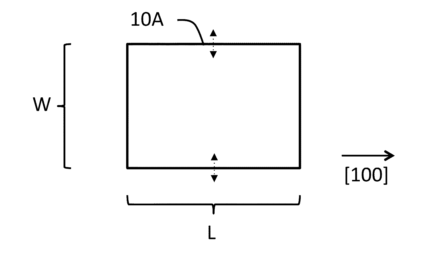
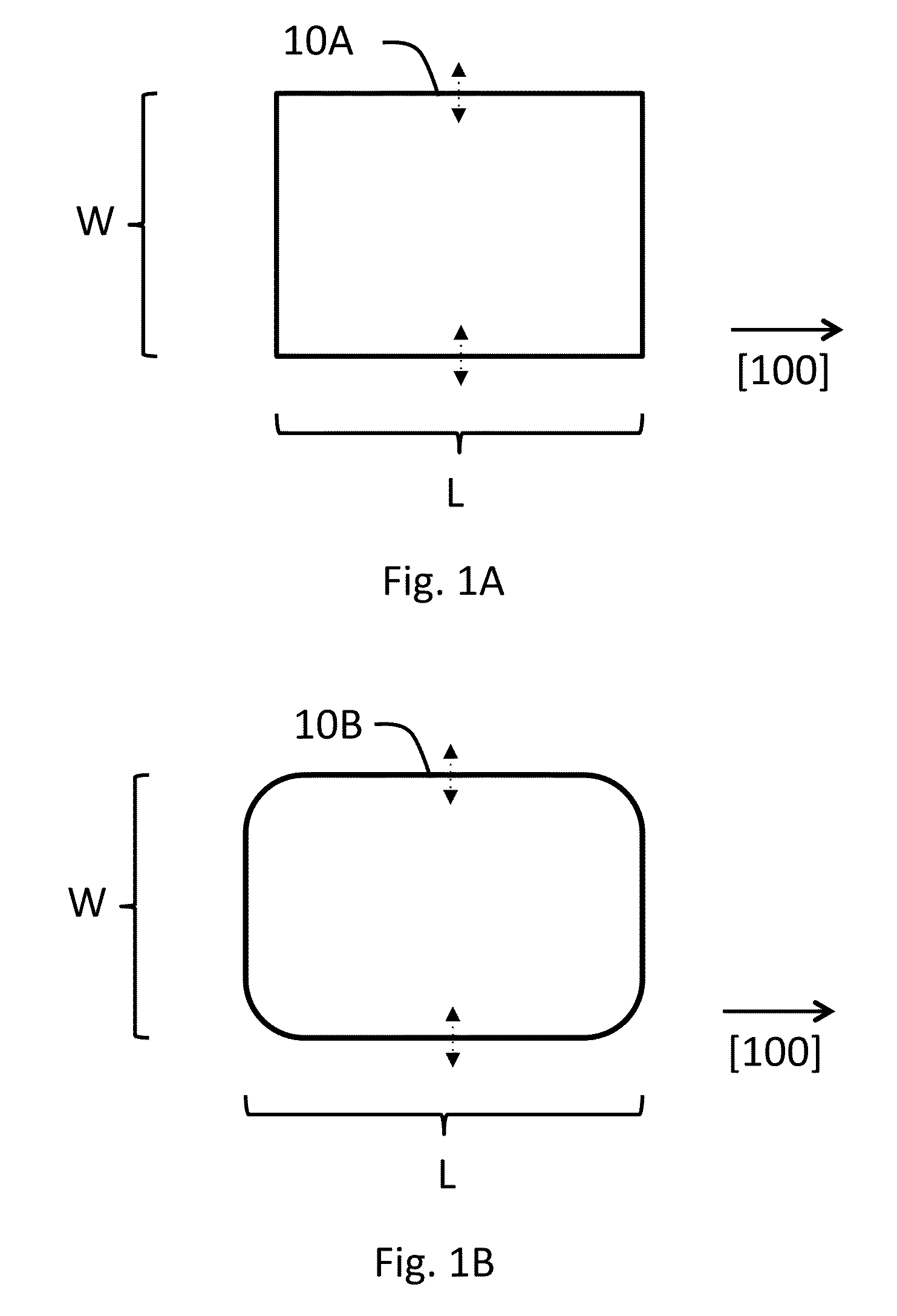
[0052]FIG. 1 shows a rectangular resonator plate 10A having a length L and width W. The longer sides of the plate 10A are oriented along the [100] direction of the silicon crystal. Main deformation direction of the resonator plate 10A in a WE resonance mode is along the width axis of the plate and is illustrated with dashed arrows. Preferably, the deformation is symmetrical with respect to the longitudinal axis of the plate 10A.

[0053]FIG. 1B shows resonator plate 10B also having a generally rectangular shape but having rounded corners. Apart from this, the resonator is similar to and also operates similarly to that of FIG. 1A.

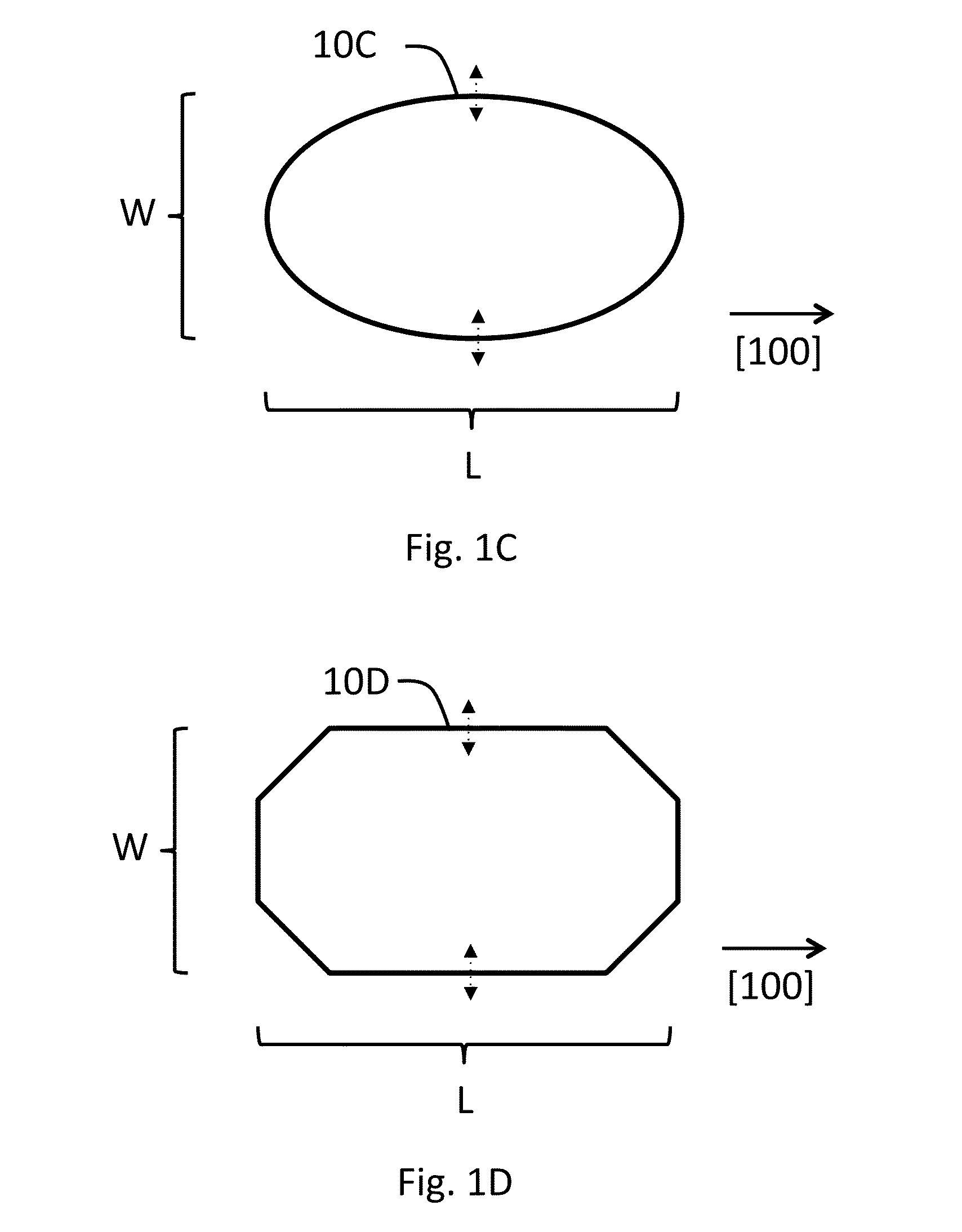
[0054]FIG. 1C shows an elliptical resonator plate 10C as another embodiment. The longer main axis of the plate has a length of L and the shorter a length of W. Optimal values and ratio of L and W may differ from those of FIGS. 1A and 1B. The elliptical plate can also resonate in a width-extensional mode, that is, along the direction of the shorter main axis.

[00...


PUM


Abstract

The invention relates to a microelectromechanical resonator device comprising a support structure and a semiconductor resonator plate doped to a doping concentration with an n-type doping agent and being capable of resonating in a width-extensional resonance mode. In addition, there is at least one anchor suspending the resonator plate to the support structure and an actuator for exciting the width-extensional resonance mode into the resonator plate. According to the invention, the resonator plate is doped to a doping concentration of 1.2*1020 cm−3 or more and has a shape which, in combination with said doping concentration and in said width-extensional resonance mode, provides the second order temperature coefficient of frequency (TCF2) to be 12 ppb / C2 or less at least at one temperature. Several practical implementations are presented.

Description

FIELD OF THE INVENTION[0001]The invention relates to microelectromechanical resonators. In particular, the invention relates to adjusting temperature coefficient of frequency (TCF) of plate resonators.BACKGROUND OF THE INVENTION[0002]Widely used quartz crystal based resonators can potentially be replaced by micromechanieal, typically silicon-based, resonators in many applications. Silicon resonators can be made smaller than quartz resonators and there are a plurality standard manufacturing methods for silicon resonators. However, a problem associated with silicon based resonators is that they have a high temperature drift of the resonance frequency. The drift is mainly due to the temperature dependence of the Young modulus of silicon, which causes a temperature coefficient of frequency (TCF) approx. −30 ppm / C. This causes the resonance frequency to fluctuate due to changes in ambient temperature.[0003]As concerns the TCF, both the linear, i.e. 1st order, and 2nd order behaviors are ...

Claims


Application Information

Patent Timeline
IPC IPC(8): H03H9/17H01L41/18
CPCH01L41/18H03H9/17H03H9/02448H03H9/2436H03H2009/2442H03H2009/02527H03H2009/02503H10N30/85
Inventor JAAKKOLA, ANTTIPEKKO, PANUPRUNNILA, MIKAPENSALA, TUOMAS
Owner TEKNOLOGIAN TUTKIMUSKESKUS VTT OY
Why Eureka
Try Eureka