
Methods relating to monitoring fuel cells

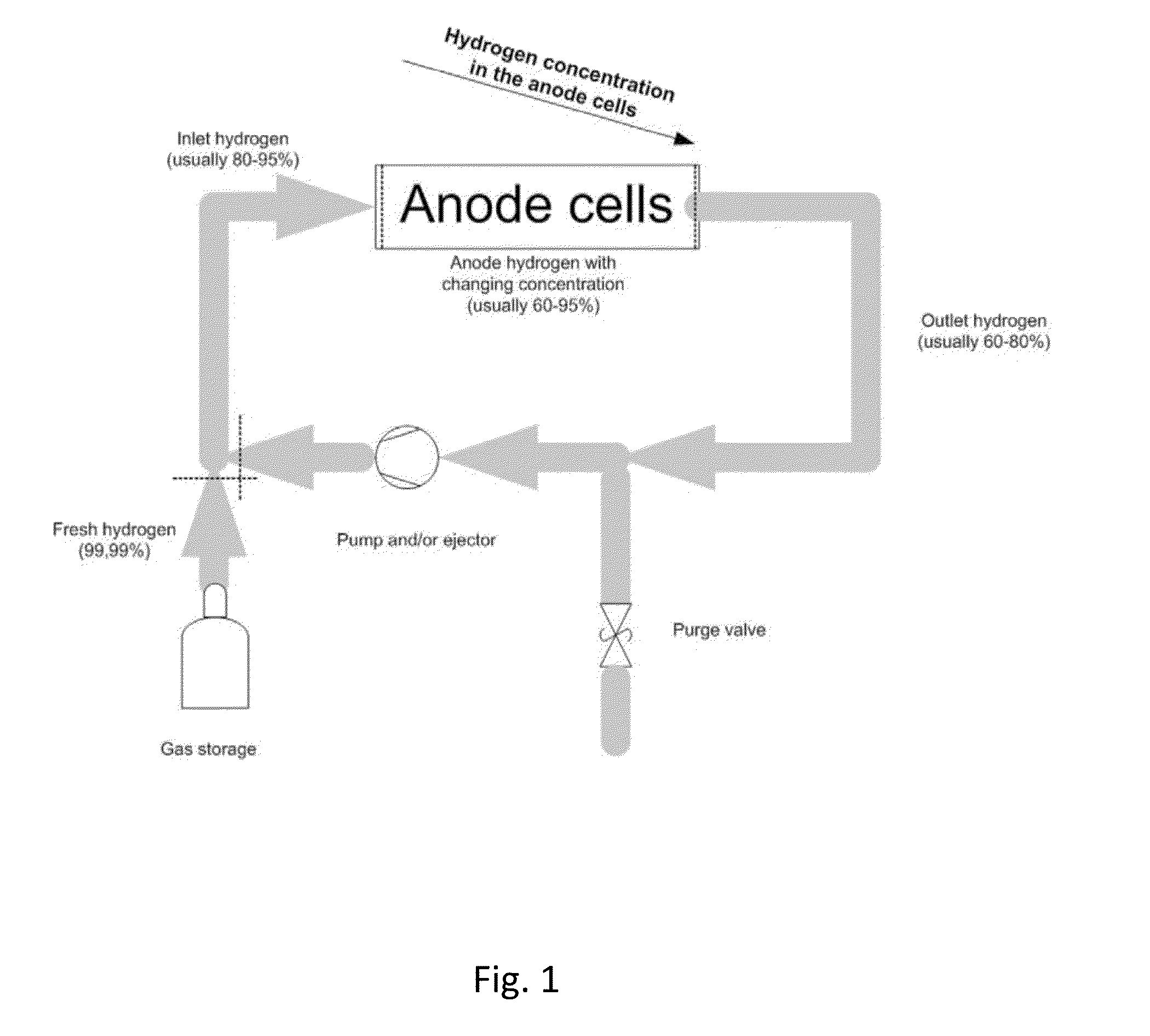
a fuel cell and monitoring technology, applied in the field of fuel cells, can solve the problems of low pressure drop, no practical and accurate method for measuring the removal of water, and only possible use of differential pressure, and achieve the effect of low power operation

Active Publication Date: 2016-04-07
TEKNOLOGIAN TUTKIMUSKESKUS VTT
View PDF6 Cites 5 Cited by
  • Summary
  • Abstract
  • Description
  • Claims
  • Application Information

AI Technical Summary

Benefits of technology

The patent is about a method to detect water accumulation in fuel cells using short hydrogen purges. The method can be used at low load levels of the fuel cell and is particularly useful during shut-down sequences. It can be easily integrated into existing fuel cell systems without needing any additional instrumentation or programming work, which makes it cost-effective and beneficial for fuel cell developers. Additionally, the method can also improve fuel cell performance analysis by measuring fuel consumption.

Problems solved by technology

However, there is no practical and accurate method for measurement for the removal of water, especially when the pressure drop over the anode is small.
However, the use of differential pressure is only possible if the flow rate on the anode gas remains constant and if the pressure difference is large enough.
When recirculation rate is low (pump used, instead of ejector) the pressure drop is low and use of pressure signal is more difficult.
In addition, if diaphragm type of pump is used, the pulsing flow makes the use of pressure signal more difficult to measure.
Thus, there is a need for determining water accumulation at low load levels, this being difficult with traditional measurements (pressure drop dP between inlet and outlet).
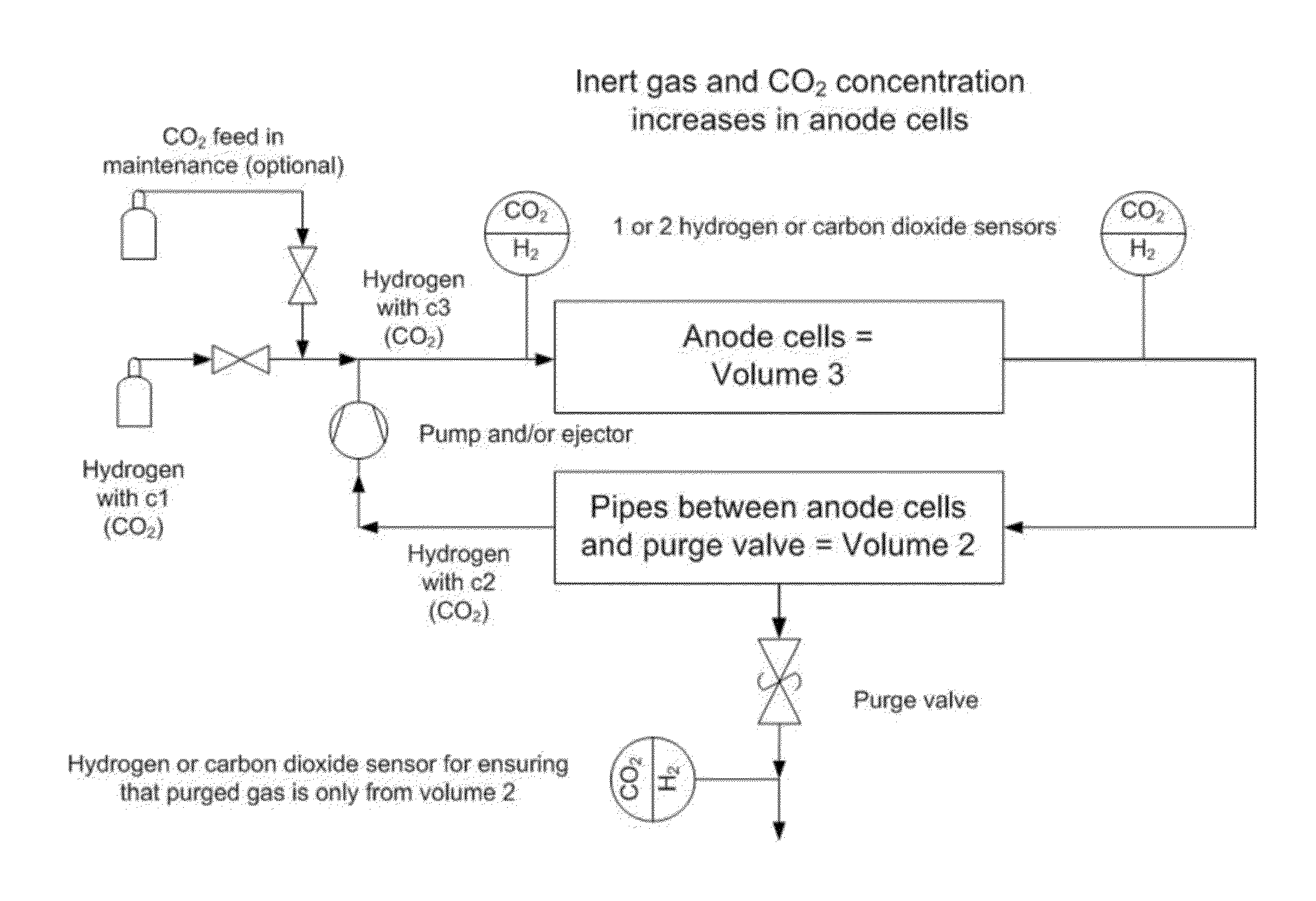
To mention further problems relating to PEFC systems, hydrogen, which is consumed in hydrogen fuel cell system, contains always some amount of inert gases including also carbon dioxide.
Further, in fuel cells operating at dead-end mode the real fuel utilization is very difficult to measure on-line or during annual maintenance.
However, in commercial fuel cell systems the required instrumentation is far too expensive.
Fuel efficiency is not accurately measured on-line in existing fuel cell systems.
For this reason, determination of PEFC system aging, to mention one example, is difficult.

Method used


Image

  • Methods relating to monitoring fuel cells
  • Methods relating to monitoring fuel cells
  • Methods relating to monitoring fuel cells

Examples


Embodiment Construction

[0061]Multiple purge method for detecting water accumulation in anode gas channels

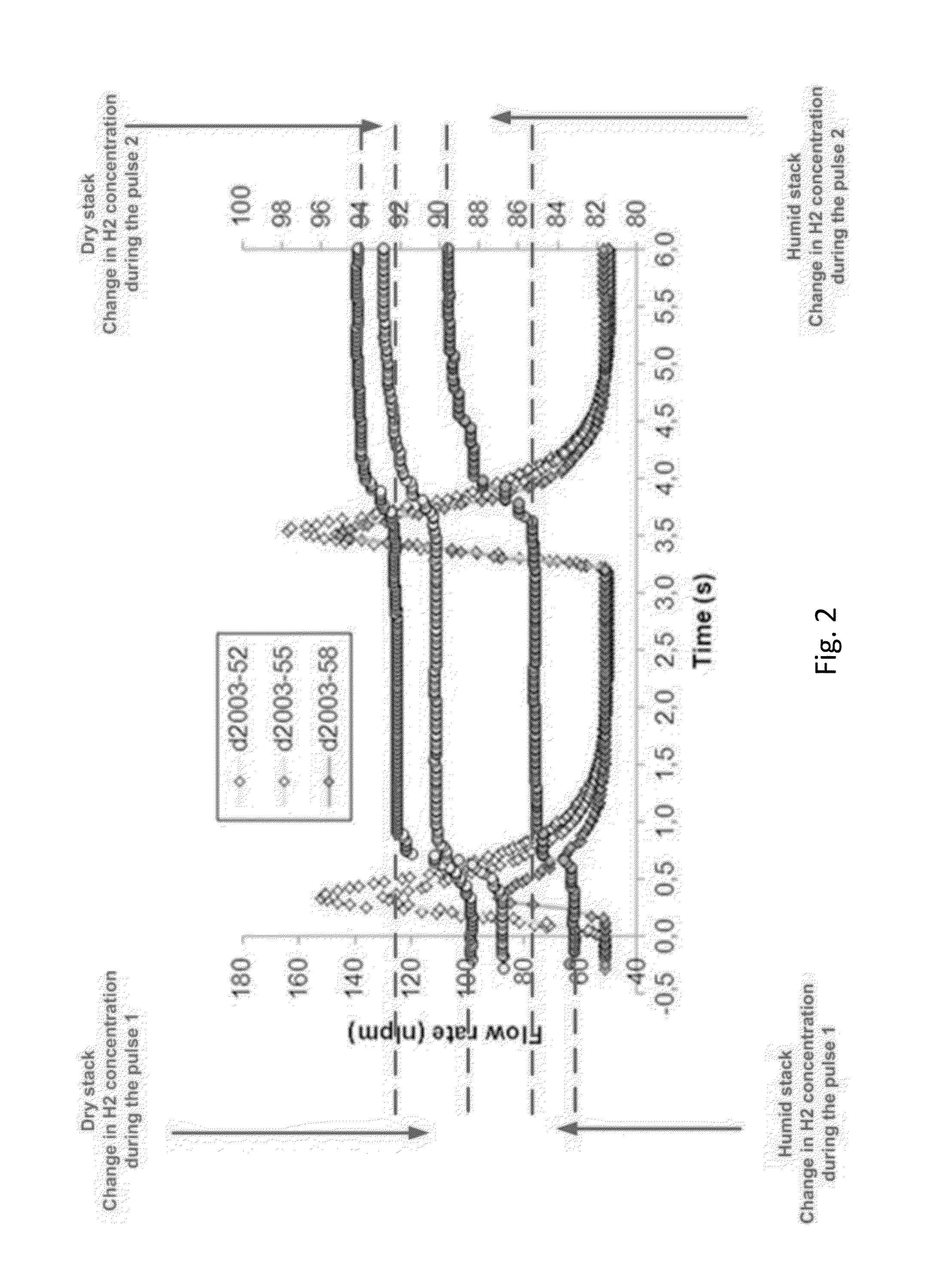
[0062]The water accumulation in anode channels is important to measure to optimize the duration and the frequency of purge during normal operation. In addition, the change (increase) in water accumulation under the same operation conditions can be used as diagnostic tool to estimate aging of the bipolar plate and GDL as aging of these components will increase water accumulation.

[0063]The practicality and accuracy of the method in this innovation can evaluated against the differential pressure drop method assuming pressure drop is large enough in the anode side of the stack.

[0064]The innovation can also be used for detection of bipolar plate and GDL aging on the cathode side, if fuel cell is arranged so that anode and cathode are interchanged.

[0065]However, the aging of cathode side components is easily seen from the pressure drop data. Pressure drop on the cathode side is significantly larger and the g...


PUM

PropertyMeasurementUnit
time periodaaaaaaaaaa
pressure dropaaaaaaaaaa
timeaaaaaaaaaa

Abstract

The invention relates to a method of determining water accumulation in and or removal from a fuel cell, the method comprising circulating fuel gas in the anode side of the fuel cell for producing electric energy in a fuel cell process, providing at least two purge pulses from the fuel circulation, analyzing the composition and / or volume of purged gas of said at least two gas purge pulses for determining the amount of water accumulation in and / or removal from the fuel cell.

Description

FIELD OF THE INVENTION[0001]The invention relates to fuel cells. In particular, the invention relates to determining water accumulation in the anode side of a polymer electrolyte fuel cell (PEFC) and determining fuel cell system performance. The invention also relates to corresponding fuel cells.BACKGROUND OF THE INVENTION[0002]In fuel cells operating at dead-end mode there is accumulation of both inert gas and water on the anode side of the cell. Water is accumulated in the channels and it is periodically removed by so called “hydrogen purge”, by opening the exit valve of the anode side for a short period of time.[0003]The hydrogen purge has a dual function. It removes both accumulated inert gas as well as water from anode channels. The removal of inert gas can be directly measured using a hydrogen concentration sensor. However, there is no practical and accurate method for measurement for the removal of water, especially when the pressure drop over the anode is small. If the press...

Claims


Application Information

Patent Timeline
Patent Type & Authority Applications(United States)
IPC IPC(8): H01M8/04H01M8/10
CPCH01M8/04514H01M8/1018H01M8/04179H01M2008/1095H01M2250/20H01M2300/0082H01M8/04462H01M8/04097Y02E60/50Y02T90/40
Inventor IHONEN, JARINIKIFOROW, KAJKARIMAKI, HENRIKERANEN, TIMO
Owner TEKNOLOGIAN TUTKIMUSKESKUS VTT
Learn More