
Protection Element

Active Publication Date: 2016-04-07
LITTELFUSE JAPAN GK
View PDF16 Cites 5 Cited by
  • Summary
  • Abstract
  • Description
  • Claims
  • Application Information

AI Technical Summary

Benefits of technology

The protection device described in this patent has layers of metal on both sides of a special material called PTC laminar element, which can conduct electricity. These layers are connected by a fuse layer, which allows a large amount of current to flow through it. When there is too much current, the fuse layer gets overwhelmed and the current flows through the PTC laminar element, causing it to overheat and switch to a protective state. This stops the current from causing damage. Additionally, the protection device redirects the current into the PTC element, reducing the risk of fire. It also has a reset function, making it easier to fix any mistakes in its resistance after a sudden surge of power.

Problems solved by technology

However, a commercially available PTC component is disadvantageous compared to a fuse device consisting of a metal when a large amount of current is passed through the PTC component it because the PTC component has a larger resistance than the metal.
However, when the spacer is used, there is a problem that a protection from the excessive current cannot be ensured.
However, since the fuse device is not directly disposed in a cell inside but is disposed on a side surface of the battery or a connecting portion between the batteries, there is a disadvantage that a battery pack becomes larger.
In addition, when an excessive current is passed through a circuit, the fuse device protects the circuit by blowing (fusing) to interrupt the excessive current, while there is a disadvantage that once the fuse device blows, the cell cannot be used.

Method used


Image

  • Protection Element
  • Protection Element
  • Protection Element

Examples


example 1

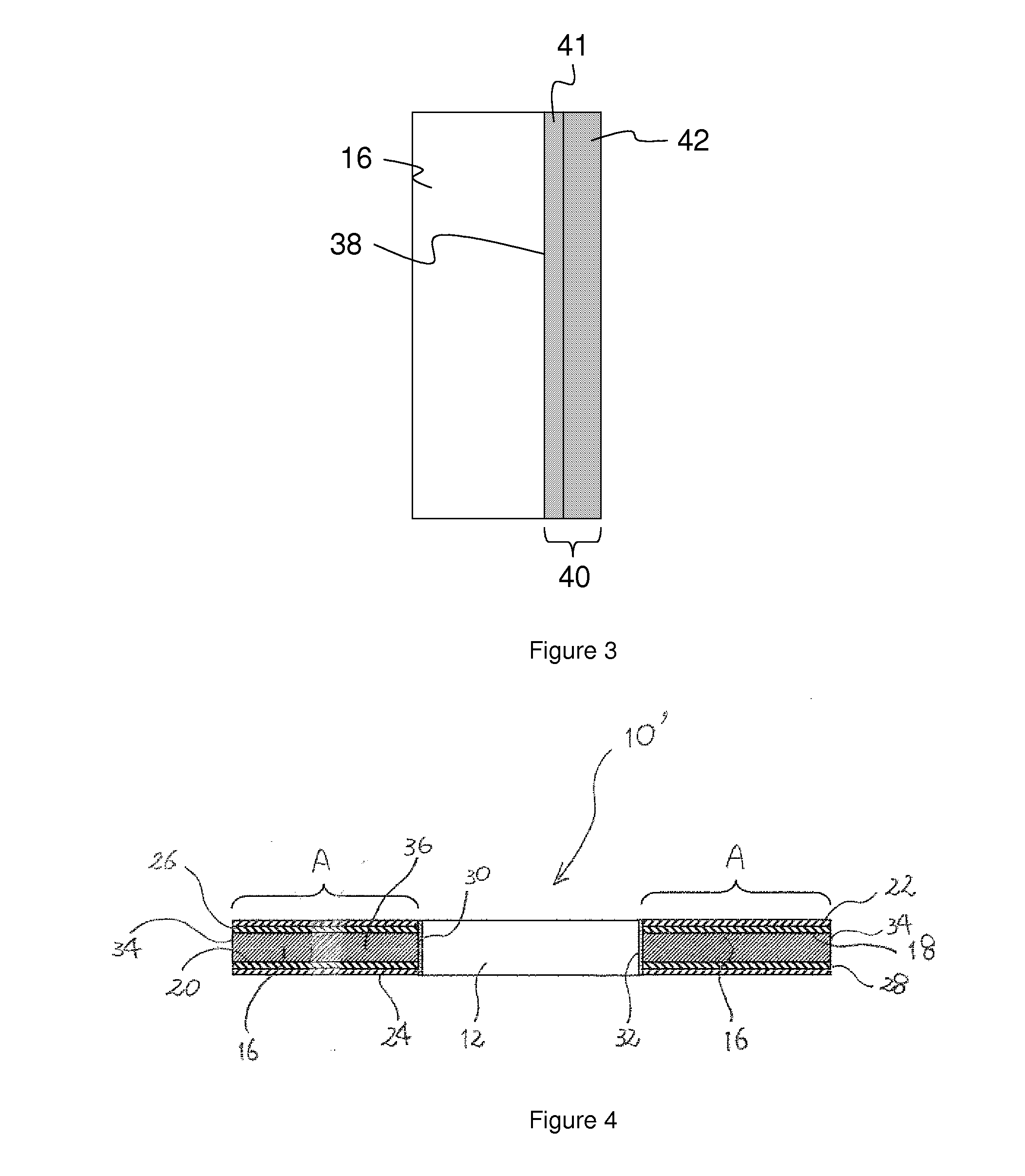
[0064]The protection device of the present invention shown in FIGS. 1 and 2 was produced. Therefore, the protection device 10 was produced which has only the fuse layer 40 but does not have the fuse layer 32. It is noted that eight surrounding throughholes 14 were circumferentially formed at an equal angle interval.

[0065]First, a sheet (a thickness of 0.3 mm; corresponding to the laminar element 16) of PTC composition (a high density polyethylene containing a carbon black particulate material) was prepared, nickel foils (having a thickness of 22 μm, corresponding to the separate metal layers 26 and 28) were positioned on the both side of the sheet, and they were pressed while heating to be integral to obtain a pressure-bonded product wherein the nickel foils were applied to the both main surfaces.

[0066]Throughholes (corresponding to the surrounding throughhole 14) which were of 0.6 mm in a diameter were formed at prescribed positions of the pressure-bonded product, and then plating ...

example 2

[0068]The protection device of the present invention was obtained similarly to Example 1 except that plating process after the formation of the throughholes (corresponding to the surrounding throughholes) was performed by Ni-plating with an electroless plating process and Sn-plating with an electrolytic plating process to obtain a nickel layer having a thickness of about 1.5 μm (corresponding the first metal layer 41) and an Sn layer having a thickness of about 6.5 μm (corresponding the second metal layer 42).

experiment 1

(Experiment 1)

[0069]A current (with 60 Vdc) listed in following Table 1 was passed through the protection device of Examples 1 and 2 from one electrically conductive metal thin layer 22 to the other electrically conductive metal thin layer 24. The maximum value of current which continues to flow without blowing for 10 minutes was defined as “rated capacity”. As a result, the rated capacity of the protection device of Example 1 was 25 A and the rated capacity of the protection device of Example 2 was 22.5 A.


PUM


Abstract

The present invention provides a protection device which includes: a PTC laminar element which is formed of an insulation resin and has at least one throughhole; electrically conductive metal thin layers which are positioned on each of main surfaces of the laminar element, and a fuse layer which is positioned on a side surface defining at least one of said at least one throughhole and electrically connects the electrically conductive metal thin layers which are positioned on each of main surfaces of the laminar element. The protection device of the present invention allows a larger amount of a current to flow therethrough and can provide a protection from an excessive current.

Description

TECHNICAL FIELD[0001]The present invention relates to a protection device which protects an electrical apparatus, in particular to a protection device which protects an electrical element or a circuit which is included in an electrical apparatus. For example, the present invention relates to a protection device which interrupts an excessive current when the excessive current flows through an electrical apparatus such as a secondary battery. That is, the present invention relates to an excessive current protection device.BACKGROUND ART[0002]A thermal fuse device, a current fuse device, a polymer PTC device, or the like is used as a protection device which interrupts an excessive current when the excessive current flows during charging or discharging of a cylindrical lithium-ion secondary battery. In particular, the polymer PTC device is useful in that since it can be positioned by incorporating into a sealing plate of the secondary battery, a battery pack which is particularly compos...

Claims


Application Information

Patent Timeline
IPC IPC(8): H01M2/34H01H85/08H01M10/0525H01M50/574H01M50/583
CPCH01M2/348H01H85/08H01M2200/106H01M10/0525H01M50/574H01M50/583H01C7/02H01H85/11H01H2085/025H01C7/021Y02E60/10H01M50/581
Inventor TANAKA, ARATAUSUI, HISASHINOMURA, KEIICHIRO
Owner LITTELFUSE JAPAN GK
Learn More