
Adaptive Private Network with Dynamic Conduit Process

a technology of dynamic conduit and adaptive private network, which is applied in the field of network communication improvement, can solve the problems of inability to reconfigure the network normally, inefficient and costly implementation of repeated static configuration of the network, and quality problems associated with statically configured networks, so as to improve network performance, reliability, and predictability.

Active Publication Date: 2016-03-10
TALARI NETWORKS
View PDF14 Cites 24 Cited by
  • Summary
  • Abstract
  • Description
  • Claims
  • Application Information

AI Technical Summary

Benefits of technology

The present invention provides a method to create dynamic conduits between different locations without the need for costly hardware upgrades or replacement of existing network equipment. This helps to improve performance, reliability, and predictability of networks. The invention also addresses the problem of multiple site pairs competing for dynamic conduit resources. The method involves an intermediate site that tracks local WAN link usages associated with multiple site pairs, and creates a dynamic conduit between the two sites if there is a high usage of the link. Overall, this method allows for better performance and reliability of networks without significant hardware upgrades or replacements.

Problems solved by technology

With the network system operating over time, the original assumptions on communication paths will likely change and, for example, sites A and C may require much higher bandwidth at this later time than is easily achieved by communicating through the intermediate site B thereby causing congestion on the paths between sites A and B and between sites B and C. A reconfiguration of the network is not usually feasible due to configuration overhead and lost time in operating the network.
Further, the dynamics of the network system may further change over time making repeated static configuration of the network inefficient and costly to implement.
As data flow patterns change in the network, the reserved resources create non-optimal static connections which cause the network to reserve bandwidth that could be better used elsewhere in the network.
In addition to effects on bandwidth, there are also quality issues associated with statically configured networks.
Traversing extra WAN hops can hurt quality of time sensitive applications like VOIP by adding latency and jitter.

Method used


Image

  • Adaptive Private Network with Dynamic Conduit Process
  • Adaptive Private Network with Dynamic Conduit Process
  • Adaptive Private Network with Dynamic Conduit Process

Examples


Embodiment Construction

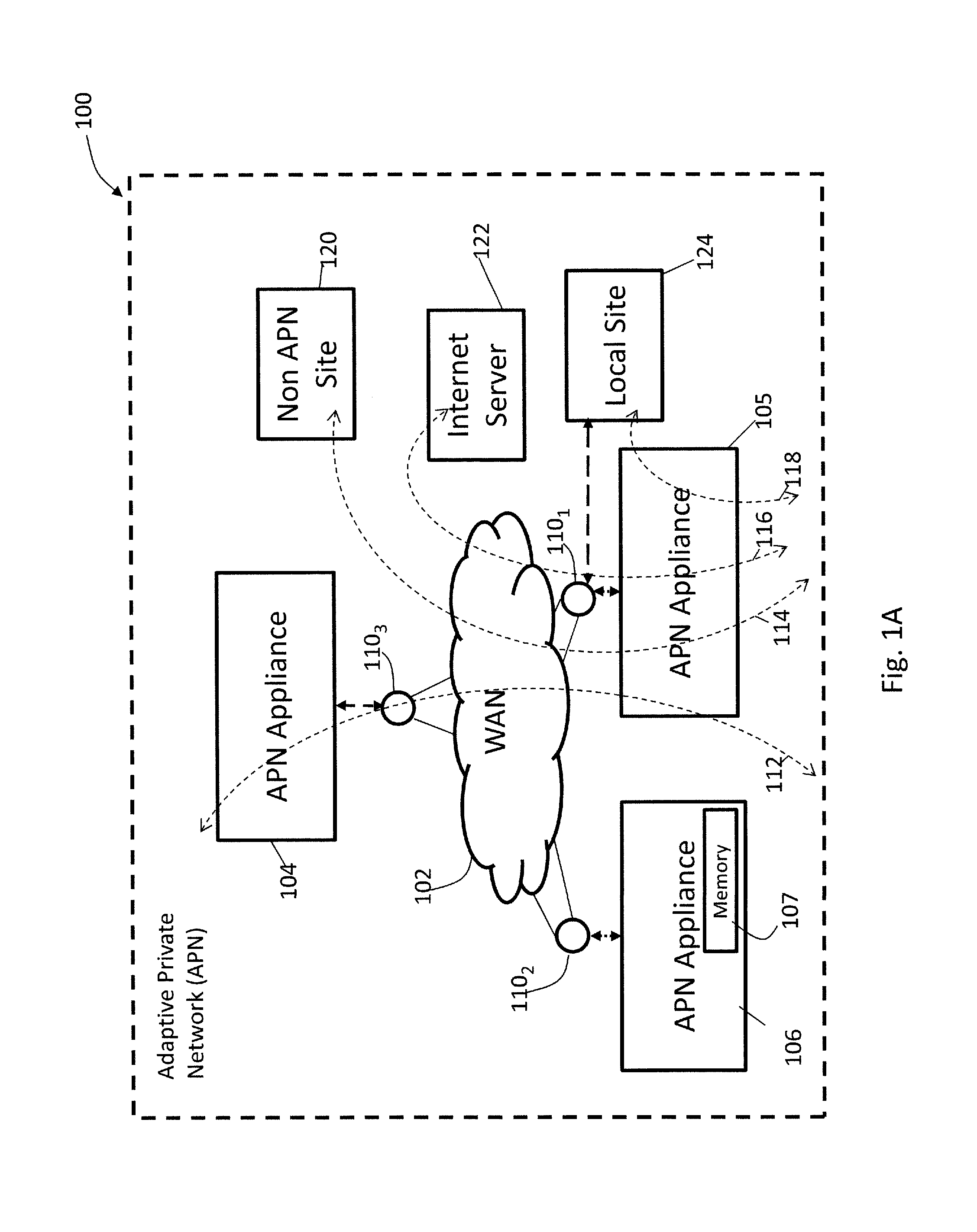
[0031]FIG. 1A shows an example of an adaptive private network (APN) 100 in which the present invention may be suitably employed as described in further detail below, including the network components, flows, paths, and services. The APN 100 includes one or more wide area networks (WANs), such as WAN 102, APN appliances 104-106, WAN routers 1101-1103, and network application services as well as APN conduits between APN appliances, as described in more detail below.

[0032]An APN path is a logical connection established between two WAN links located at different geographic sites across a WAN.

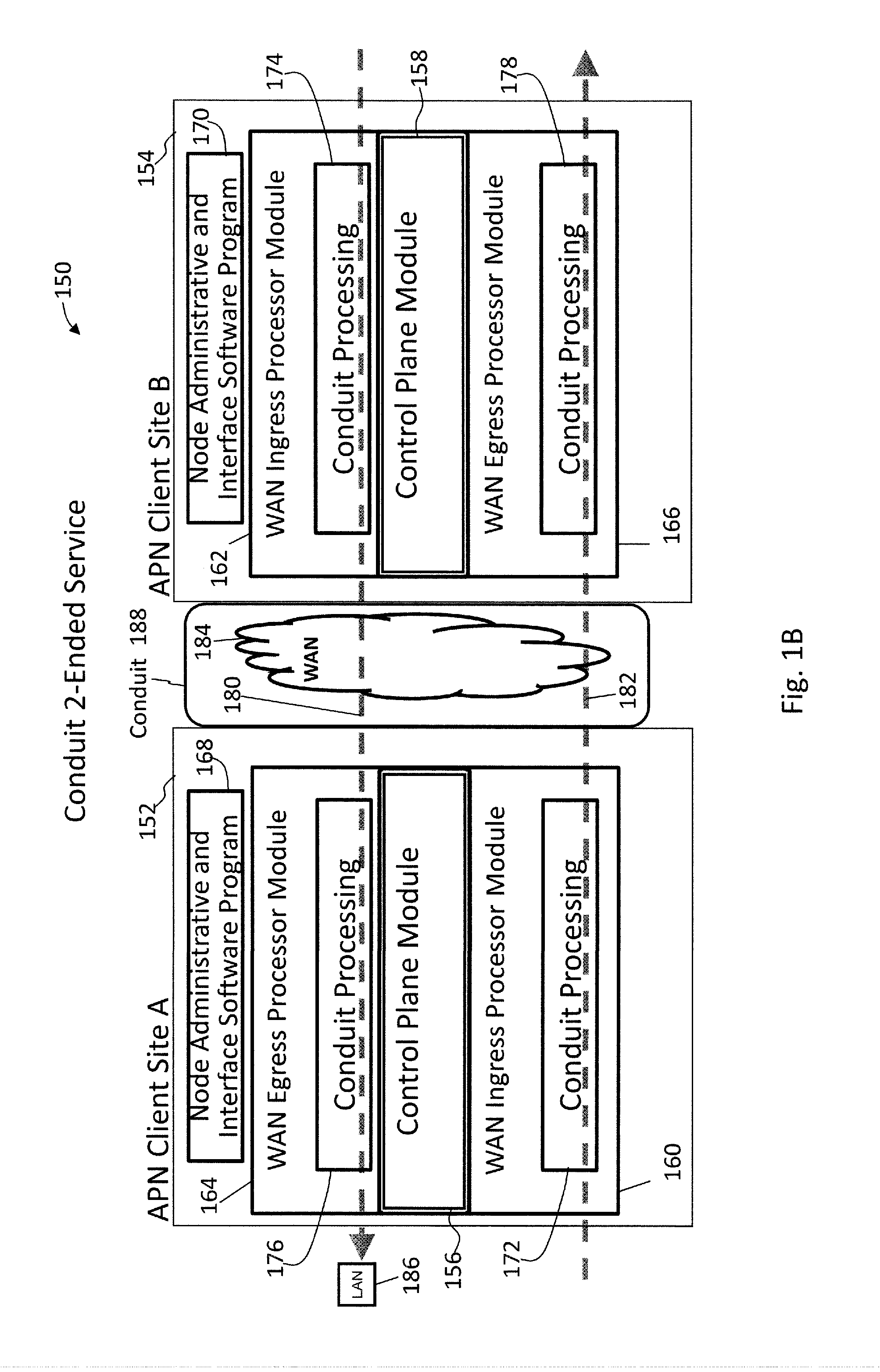
[0033]An APN conduit is a virtual connection between two APN nodes, also referred to as client sites, and formed by aggregating one or more APN paths and their allocated WAN link resources.

[0034]A conduit MTU is a minimum link MTU of the one or more APN paths between a source site and a destination site.

[0035]An APN appliance (APNA) is a device that contains APN client site functionality including al...


PUM


Abstract

Systems and techniques, including special messages and state machines, are described that configures an intermediate site to dynamically trigger creation of and removal of a dynamic conduit between two sites based on usage that is tracked at the sites. The intermediate site providing WAN-to-WAN forwarding between the two sites, monitors throughput statistics on each local WAN link (LWL) associated with the two sites. If traffic between the two sites passes a configured first threshold or if LWL usage passes a configured second threshold, the intermediate site sends a message to the two sites to set up a dynamic conduit directly coupling the two sites. Busy lists are used to keep track of eligible site pairs. Once a dynamic conduit is set up between two sites, a grow technique tests the dynamic conduit increasing communication flows between the two sites each configured sampling period before putting the conduit in normal use.

Description

CROSS REFERENCE TO RELATED APPLICATIONS[0001]U.S. Pat. No. 8,125,907 filed on Jun. 11, 2009 entitled “Flow-Based Adaptive Private Network with Multiple WAN-Paths, U.S. patent application Ser. No. 13 / 208,825 filed on Aug. 12, 2011 entitled “Adaptive Private Network Asynchronous Distributed Shared Memory Services”, and U.S. patent application Ser. No. 13 / 719,433 filed on Dec. 19, 2012 entitled “An Adaptive Private Network with Geographically Diverse Network Control Nodes” have the same assignee as the present application, are related applications, and are hereby incorporated by reference in their entirety.FIELD OF THE INVENTION[0002]The present invention relates generally to improved network communication. More specifically, the present invention relates to improved communication path bandwidth and reduction in communication path length through a dynamic conduit process.BACKGROUND OF THE INVENTION[0003]The introduction of frame relay in the early 1990's brought lower cost, higher band...

Claims


Application Information

Patent Timeline
Patent Type & Authority Applications(United States)
IPC IPC(8): H04L47/36H04L45/02
CPCH04L45/40H04W84/12H04L45/10H04L69/28H04L41/0659H04L43/0858G06F11/2002G06F11/1464G06F11/0709H04L47/365G06F11/2005G06F2201/86H04L41/12H04L67/12H04L43/10H04L45/26H04L47/28H04L47/34
Inventor HUANG, WEIMARTIN, TODDPATTERSON, JUSTIN ALLENDICKEY, III, ROBERT W.GALLO, ANTHONY MATTEO
Owner TALARI NETWORKS
Learn More