Encoder scale and method of manufacturing the same

a technology of encoder scale and encoder body, which is applied in the direction of instruments, measuring devices, coils, etc., can solve the problems of unfavorable manufacturing processes, high electrostatic charge of substrate, unfavorable electrical discharge and/or noise, etc., and achieve the effect of reducing manufacturing processes

Active Publication Date: 2016-02-25
MITUTOYO CORP
View PDF2 Cites 4 Cited by
  • Summary
  • Abstract
  • Description
  • Claims
  • Application Information

AI Technical Summary

Benefits of technology

[0033]As compared with the method of manufacturing the typical encoder scale, the method of the second aspect does not require several processes for forming an antistatic electrode for grounding on the substrate and a process for partly removing the electroconductive layer. The manufacturing processes can thus be reduced.

Problems solved by technology

However, the substrate of the insulating body is likely to be electrostatically charged.
Electrostatic charge of the substrate, which causes electrical discharge and / or noise, is unfavorable.

Method used


Image

  • Encoder scale and method of manufacturing the same
  • Encoder scale and method of manufacturing the same
  • Encoder scale and method of manufacturing the same

Examples


Embodiment Construction

)

[0049]Exemplary embodiment(s) of the invention will be described below with reference to the attached drawings.

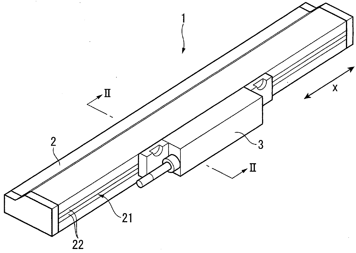
[0050]FIG. 1 is a perspective view showing an electromagnetic induction linear encoder 1 provided with an encoder scale 4 according to an exemplary embodiment of the invention. The electromagnetic induction linear encoder 1 (an electromagnetic induction encoder) includes: a main scale 2 extending in a measurement direction X; and an encoder head 3 provided to be movable relative to the main scale 2 in the measurement direction X.

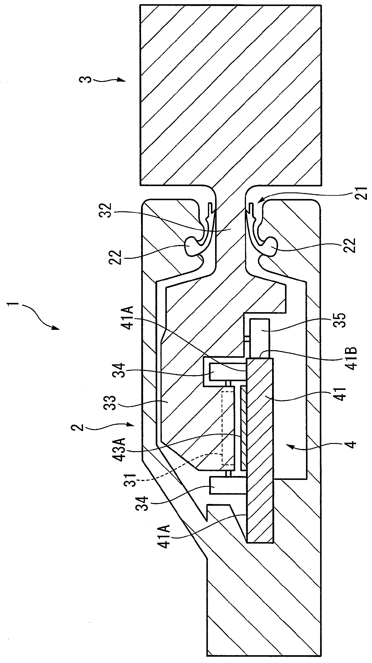
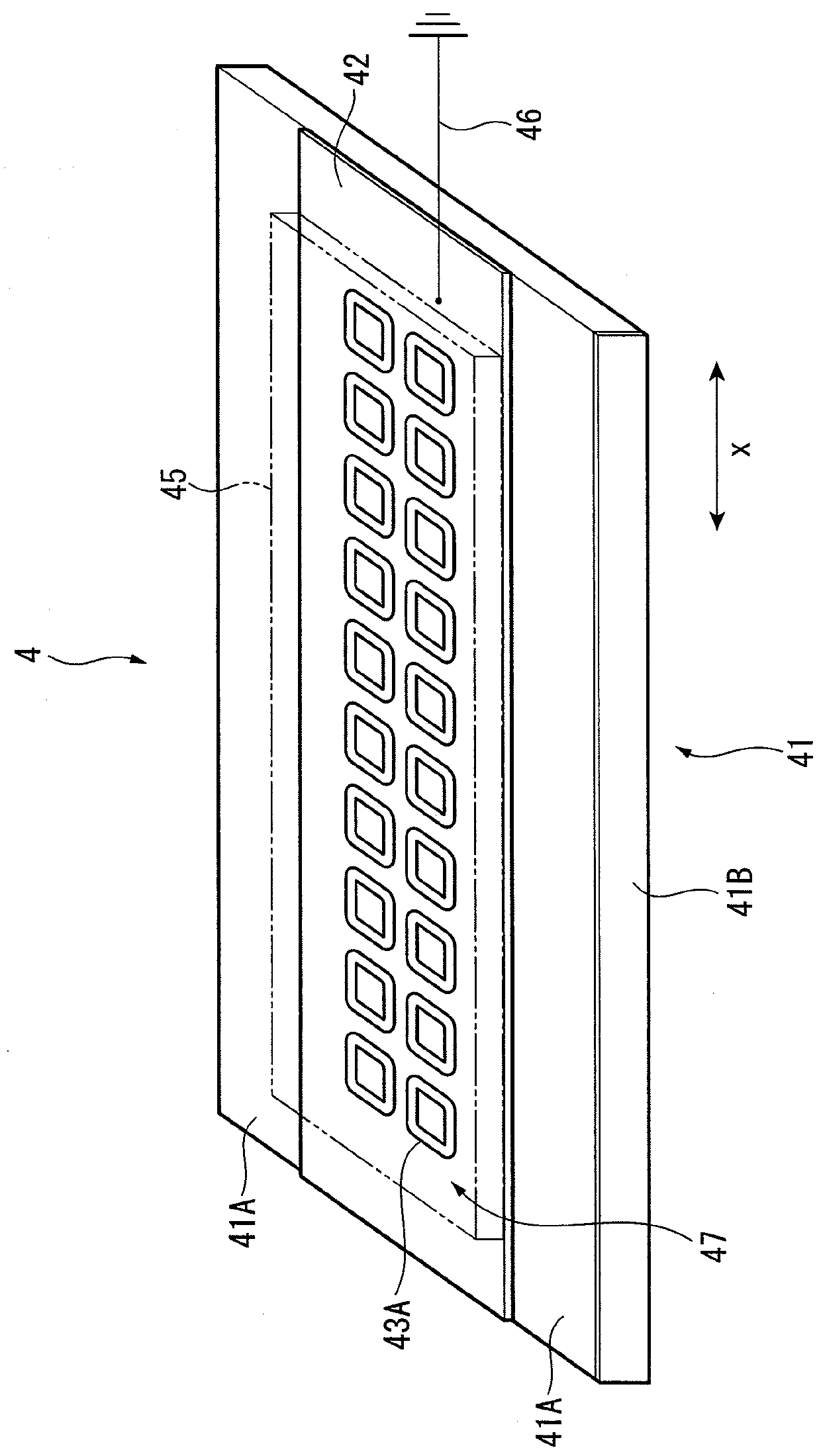
[0051]As shown in FIG. 2, the encoder scale 4 is provided in the main scale 2, and a portion of the encoder head 3 facing the encoder scale 4 is provided with a pick-up coil 31. In the electromagnetic induction linear encoder 1, electromagnetic induction is caused between the pick-up coil 31 and an electric conductor 43A (see FIGS. 3 and 4A to 4D) forming an induction electrode to generate an induced electromotive force in the pick-up coil 31. A po...


PUM


Abstract

An encoder scale for an electromagnetic induction linear encoder includes a substrate, an electroconductive layer exhibiting electroconductivity and provided to one surface of the substrate, and an electric conductor provided on the electroconductive layer. The electroconductive layer is wider than the electric conductor in a plan view of the substrate and is grounded. The electroconductive layer is formed on the entire one surface of the substrate except a guide surface, and glass is exposed on the guide surface.

Description

[0001]The entire disclosure of Japanese Patent Application No. 2014-166654 filed Aug. 19, 2014 is expressly incorporated by reference herein.FIELD OF THE INVENTION[0002]The present invention relates to an encoder scale and a method of manufacturing the encoder scale. In particular, the present invention relates to an encoder scale for an electromagnetic induction linear encoder.BACKGROUND ART[0003]A linear encoder is known as a device that is attached to a manufacturing machine or a measuring machine to detect a position of a linearly movable unit. There are a variety of linear encoders such as an optical linear encoder, a capacitive linear encoder and an electromagnetic induction linear encoder, which employ different detection methods. In particular, as typical electromagnetic induction linear encoders, for instance, devices disclosed in Patent Literature 1 (JP-A-2009-276306) and Patent Literature 2 (JP-A-2011-247600) are known.[0004]The electromagnetic induction linear encoder in...

Claims


Application Information

Patent Timeline
Patent Type & Authority Applications(United States)
IPC IPC(8): G01D5/20
CPCG01D5/202
Inventor NOZAWA, YUKINARI
Owner MITUTOYO CORP
Why Eureka
Try Eureka