
Cell contact-making system for an electrochemical device

Active Publication Date: 2016-02-11
ELRINGKLINGER AG
View PDF2 Cites 39 Cited by
  • Summary
  • Abstract
  • Description
  • Claims
  • Application Information

AI Technical Summary

Benefits of technology

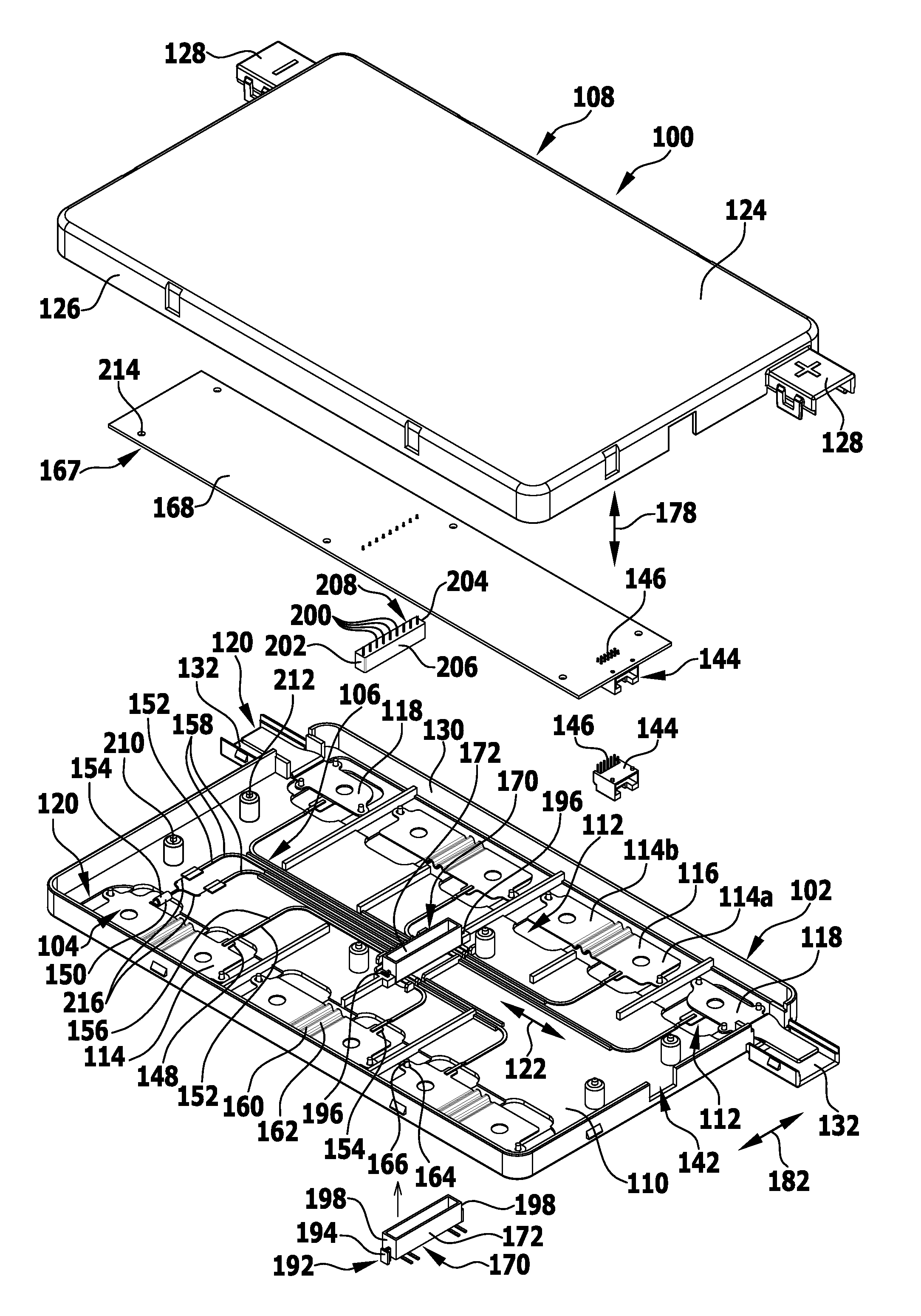
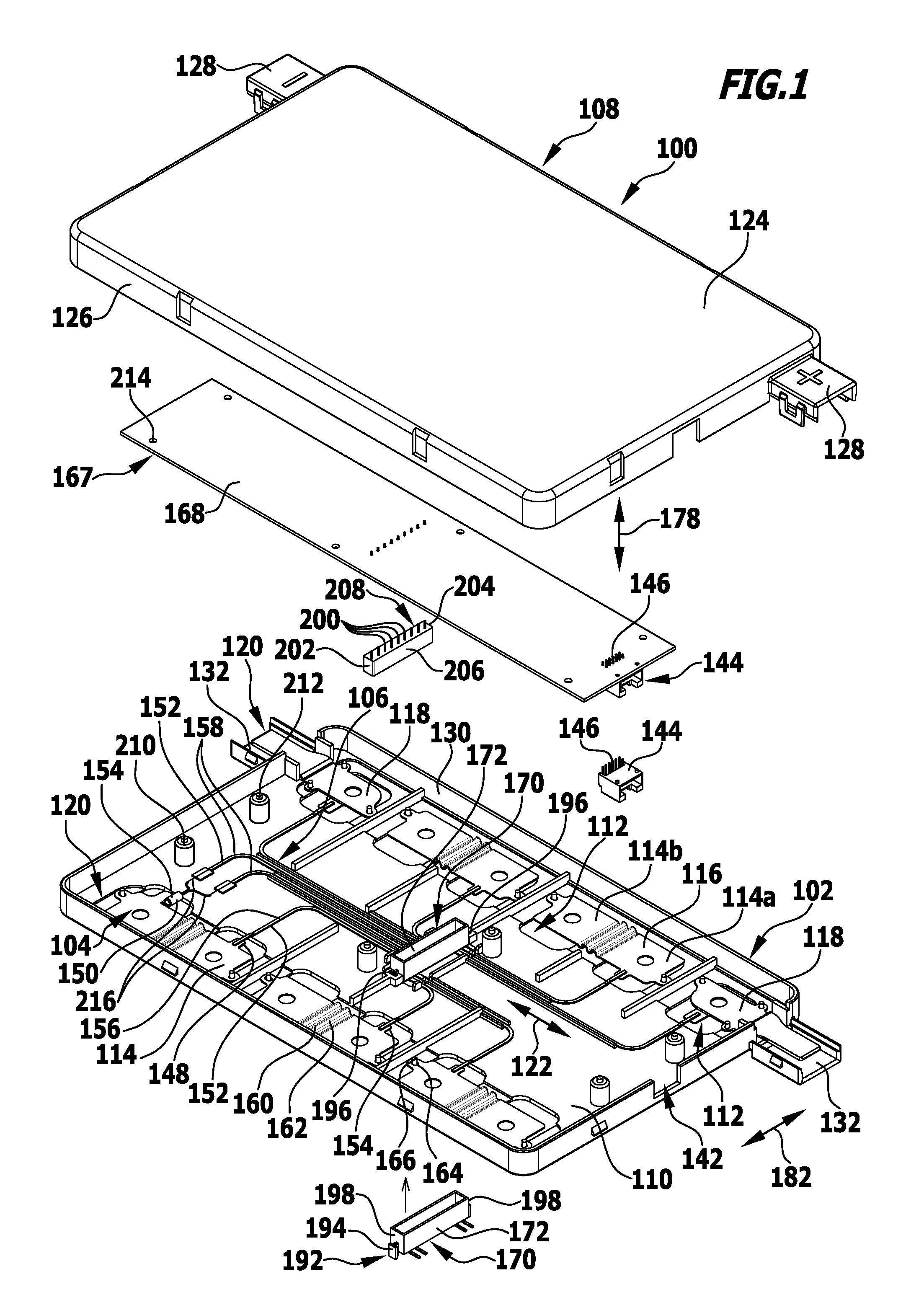
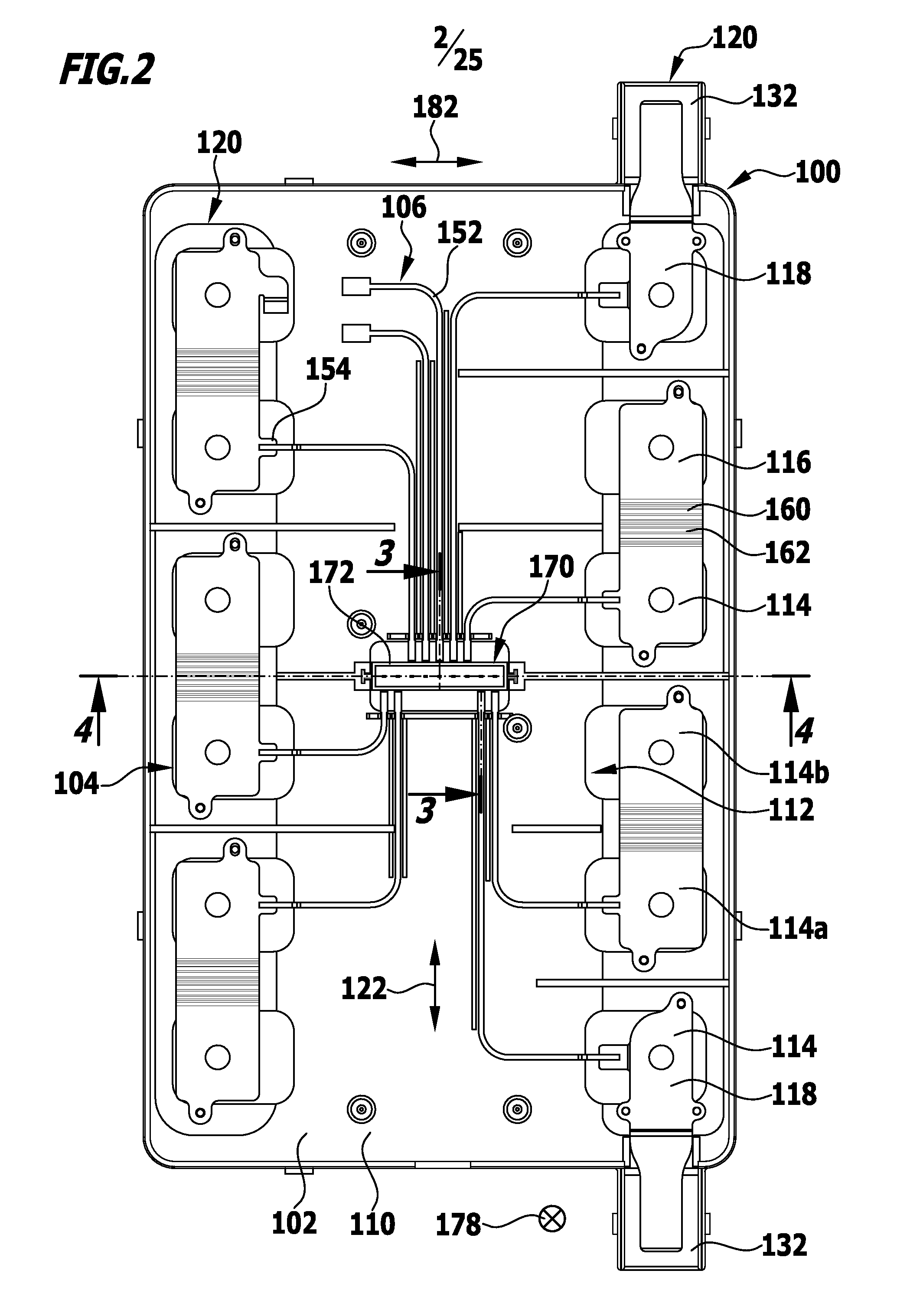
The invention is a cell contact-making system that includes a monitoring unit. The system is designed to be very compact and space-saving, and it is also very cost-effective. The monitoring unit can be easily removed for maintenance or repair purposes. The system also includes a support element and a cover element that can be releasably fixed together, allowing for a compact overall construction. The monitoring unit can be positioned in a desired position by using a positioning element on either the support element or the cover element. The cover element can also have a signal conductor terminal connector extending through it, which makes it possible to place the monitoring unit close to the signal conductor terminal connector without being positioned in an intermediate space.

Problems solved by technology

As a result, the cell contact-making system including the monitoring unit may be of very compact and space-saving construction.

Method used


Image

  • Cell contact-making system for an electrochemical device
  • Cell contact-making system for an electrochemical device
  • Cell contact-making system for an electrochemical device

Examples


second embodiment

[0175]During assembly of the cell contact-making system 100, the procedure is for example such that the cover element 108, with the housing lower part 222, is first placed, without the housing upper part 220 or the monitoring unit 167, on the support element 102 and is connected thereto, preferably releasably.

[0176]Then, the monitoring unit 167 is inserted into the monitoring unit housing 218 from above, in the vertical direction 228. During this, at the same time the plug connection between the plug contact terminal connector 208 of the monitoring unit 167 and the signal conductor terminal connector 170 of the signal conductor system 106 is made through the passage opening 244 in the cover element 108.

[0177]Finally, the housing upper part 220 is placed on the housing lower part 222 and connected thereto, in particular by being latched, with the result that the housing upper part 220 covers the monitoring unit 167 and protects it from undesired contact.

[0178]In order to remove the m...

third embodiment

[0183]In the case of the third embodiment, the housing lower part 222 is preferably formed from an electrically insulating material, in particular a synthetic material, for example PBT (polybutylene terephthalate), PP (polypropylene), PA (polyamide), ABS (acrylonitrile butadiene styrene) and / or LCP (liquid crystal polymer).

[0184]In this embodiment the plug contact terminal connector 208 of the monitoring unit 167, arranged on an underside 256 of the monitoring unit 167 that faces the base plate 254, has terminal connector pins 258 that are angled in form and each include a terminal connector portion 260 that extends in the vertical direction 228 and a contact portion 262 that extends in the longitudinal direction 122 of the cell contact-making system 100.

[0185]In this embodiment, the contact portions 262 of the terminal connector pins 258 of the plug contact terminal connector 208 of the monitoring unit 167 thus extend in a contact direction 178 that runs parallel to the plane defin...


PUM


Abstract

In order to provide a cell contact-making system for an electrochemical device which includes a plurality of electrochemical cells, wherein the cell contact-making system includes a current conductor system having one or more cell connectors, for electrically conductively connecting cell terminals of different electrochemical cells, a signal conductor system having one or more signal conductors for electrically conductively connecting a respective signal source to a signal conductor terminal connector of the cell contact-making system, and a monitoring unit for monitoring signals from the signal sources, which is of compact construction and is assemblable from a relatively small number of parts, it is proposed that the monitoring unit should include a plug contact terminal connector which is directly connectable by a plug connection to the signal conductor terminal connector of the signal conductor system.

Description

CROSS-REFERENCE TO RELATED APPLICATIONS[0001]The present application is a continuation of international application number PCT / EP2014 / 057137 filed on Apr. 9, 2014, which claims priority to German patent application number 10 2013 207 357.7 filed Apr. 23, 2013, the entire specification of both being incorporated herein by reference.FIELD OF THE DISCLOSURE[0002]The present invention relates to a cell contact-making system for an electrochemical device which includes a plurality of electrochemical cells, wherein the cell contact-making system includes a current conductor system having one or more cell connectors, for electrically conductively connecting cell terminals of different electrochemical cells,a signal conductor system having one or more signal conductors for electrically conductively connecting a respective signal source to a signal conductor terminal connector of the cell contact-making system, and a monitoring unit for monitoring signals from the signal sources.[0003]A cell...

Claims


Application Information

Patent Timeline
IPC IPC(8): H01M10/44H01M50/209H01M50/284H01M50/503H01M50/516H01M50/519H01M50/55
CPCH01M10/441H01M2/206H01M2/204H01M10/425H01M10/48H01M2010/4278B60L2240/545B60L2240/547B60L2240/549H01M10/482H01M2010/4271B60L50/64Y02T10/70Y02E60/10H01M50/519H01M50/209H01M50/284H01M50/55H01M50/503H01M50/516H01R13/6456H01R13/6608H01R12/7076
Inventor FRITZ, WOLFGANGKAZMAIER, STEFAN
Owner ELRINGKLINGER AG
Learn More