Radiation detector and method

a radiation detector and detector technology, applied in the direction of radiation intensity measurement, instruments, x/gamma/cosmic radiation measurement, etc., can solve the problems of battery operation, electronic dosimeters are expensive, and dosimeter types

Active Publication Date: 2016-02-11
MIRION TECH INC
View PDF7 Cites 2 Cited by
  • Summary
  • Abstract
  • Description
  • Claims
  • Application Information

AI Technical Summary

Benefits of technology

The patent is about a device that detects radiation by using a chamber or cavity that produces charge carriers when it is exposed to radiation. The device includes a deformable plate that moves towards a rigid plate when it is charged by an electrical voltage. When there are fewer charge carriers present, the deformable plate moves away from the rigid plate. The technical effect of this device is that it allows for the detection of radiation in a simple and effective way.

Problems solved by technology

In today's world, there is also the danger of terrorist threats using nuclear material, so military personnel and first responders need to be able to monitor their environments for these materials.
However, these types of dosimeters have a number of drawbacks.
Electronic dosimeters are expensive and require a battery to operate.
Quartz fiber dosimeters are difficult to read and have a limited measuring range.
Radiochromic dosimeters are not capable of measuring low doses of radiation and are sensitive to ambient UV radiation, temperature, and humidity, and cannot be reused.

Method used


Image

  • Radiation detector and method
  • Radiation detector and method
  • Radiation detector and method

Examples


Embodiment Construction

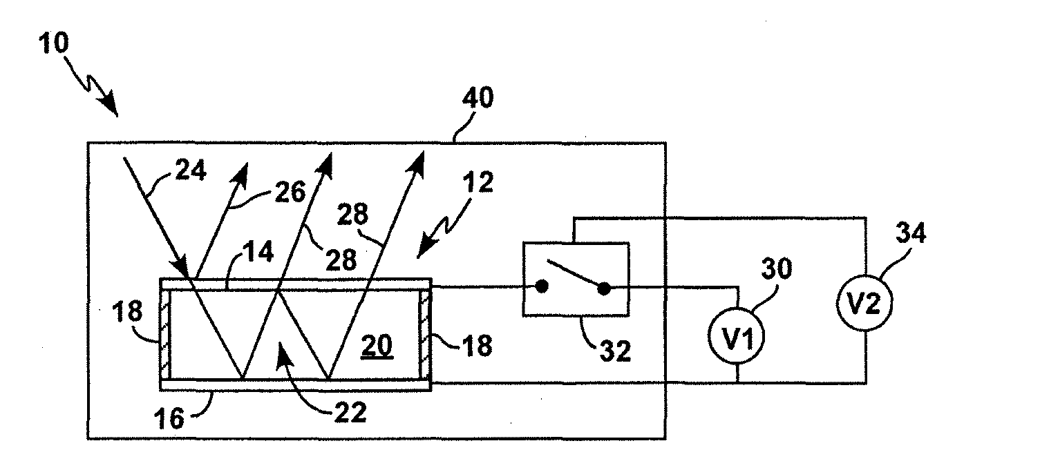
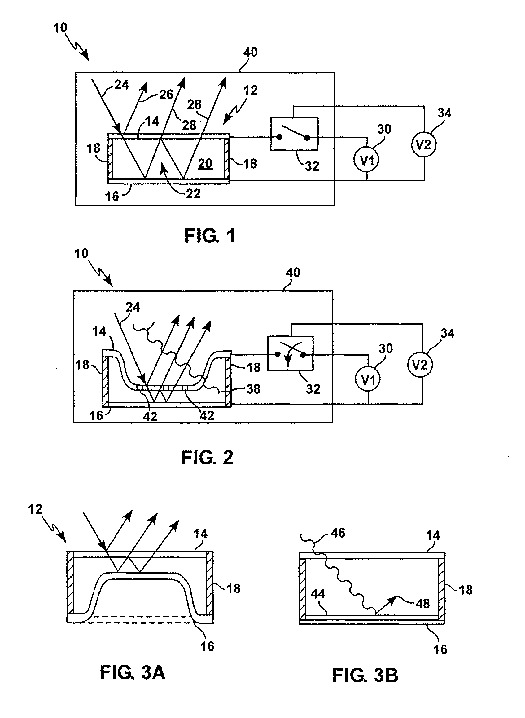
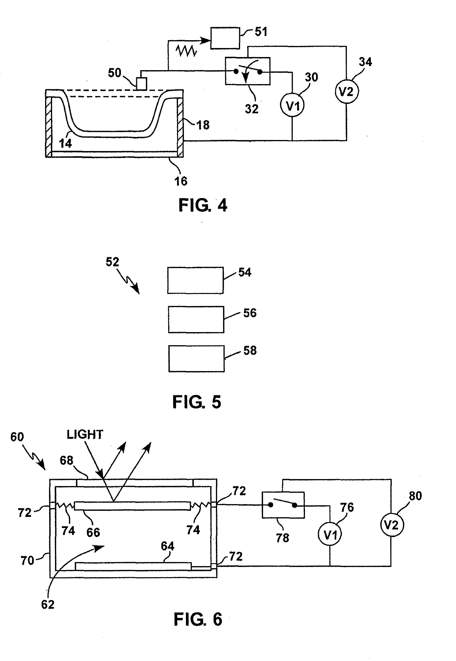
[0020]Referring more specifically to the drawings, for illustrative purposes the present technology is embodied in the apparatus generally shown in FIG. 1 through FIG. 6. It will be appreciated that the apparatus may vary as to configuration and as to details of the parts, and the method may vary as to specific sequence of steps, without departing from the basic concepts as disclosed herein.

[0021]The technology is an apparatus and method for detecting radiation in which a microelectromechanical structure (MEMS) is used to provide the readout. In one embodiment the radiation detector is configured as an interferometric modulator in which visually observed change in color indicates exposure. In a basic embodiment, the structure has two electrically conductive plates electrically insulated and separated from each other by a micromechanical spring, and the space between the plates is filled with gas. The plates are charged to different electric potentials, creating an electrostatic forc...


PUM


Abstract

Disclosed is a radiation detector, comprising a chamber or cavity that produces charge carriers when radiation is incident thereon. The chamber is defined in part by a deformable plate along one side of the chamber or cavity; and a rigid plate spaced and electrically insulated from the deformable plate. A charging voltage source is present for applying a voltage to the deformable plate; such that wherein the deformable plate is attracted toward the rigid plate by electrostatic forces when charged by the charging voltage source, and moves away from the rigid plate when charge carriers produced in the chamber or cavity by incident radiation reduce the electrostatic forces between the deformable and rigid plates.

Description

CROSS-REFERENCE TO RELATED APPLICATIONS[0001]This application is related to and claims priority to U.S. Provisional Patent Application Ser. No. 61 / 778,203 filed Mar. 12, 2013, which is hereby incorporated by reference in its entirety.BACKGROUND[0002]1. Field[0003]The present technology pertains generally to radiation detectors, and more particularly to self indicating or direct reading radiation detectors, and most particularly to radiation detectors with a direct optical visual readout.[0004]2. Description of Related Art[0005]There is a need to monitor exposure to radiation in a variety of work environments, from nuclear reactors to hospitals and other medical facilities. In today's world, there is also the danger of terrorist threats using nuclear material, so military personnel and first responders need to be able to monitor their environments for these materials.[0006]A wide variety of radiation detectors are available. Some are complex and permanently installed in a facility su...

Claims


Application Information

Patent Timeline
Patent Type & Authority Applications(United States)
IPC IPC(8): G01T1/185
CPCG01T1/185
Inventor JUKKA
Owner MIRION TECH INC
Why Eureka
Try Eureka