Aircraft

Active Publication Date: 2016-02-11
MITSUBISHI AIRCRAFT
View PDF2 Cites 6 Cited by
  • Summary
  • Abstract
  • Description
  • Claims
  • Application Information

AI Technical Summary

Benefits of technology

This patent describes a device that prevents deformation of an airframe by distributing force evenly across the area around the opening where the device penetrates. This design prevents direct force input to the opening and maintains a seal between the device and the airframe, ensuring safety and a tight seal. Additionally, the device includes a support on the opening formation member that provides a secure attachment point for other components. Overall, this invention ensures reliable airtightness and safety in the airframe even during deformation caused by aerodynamic loads.

Problems solved by technology

Since the aerodynamic load cannot be received only by a skin (an outer plate), it is difficult to achieve a configuration in which a proximal end of the arm is supported only on an outer surface side of the airframe without passing the arm through the airframe.

Method used


Image

  • Aircraft
  • Aircraft
  • Aircraft

Examples


first embodiment

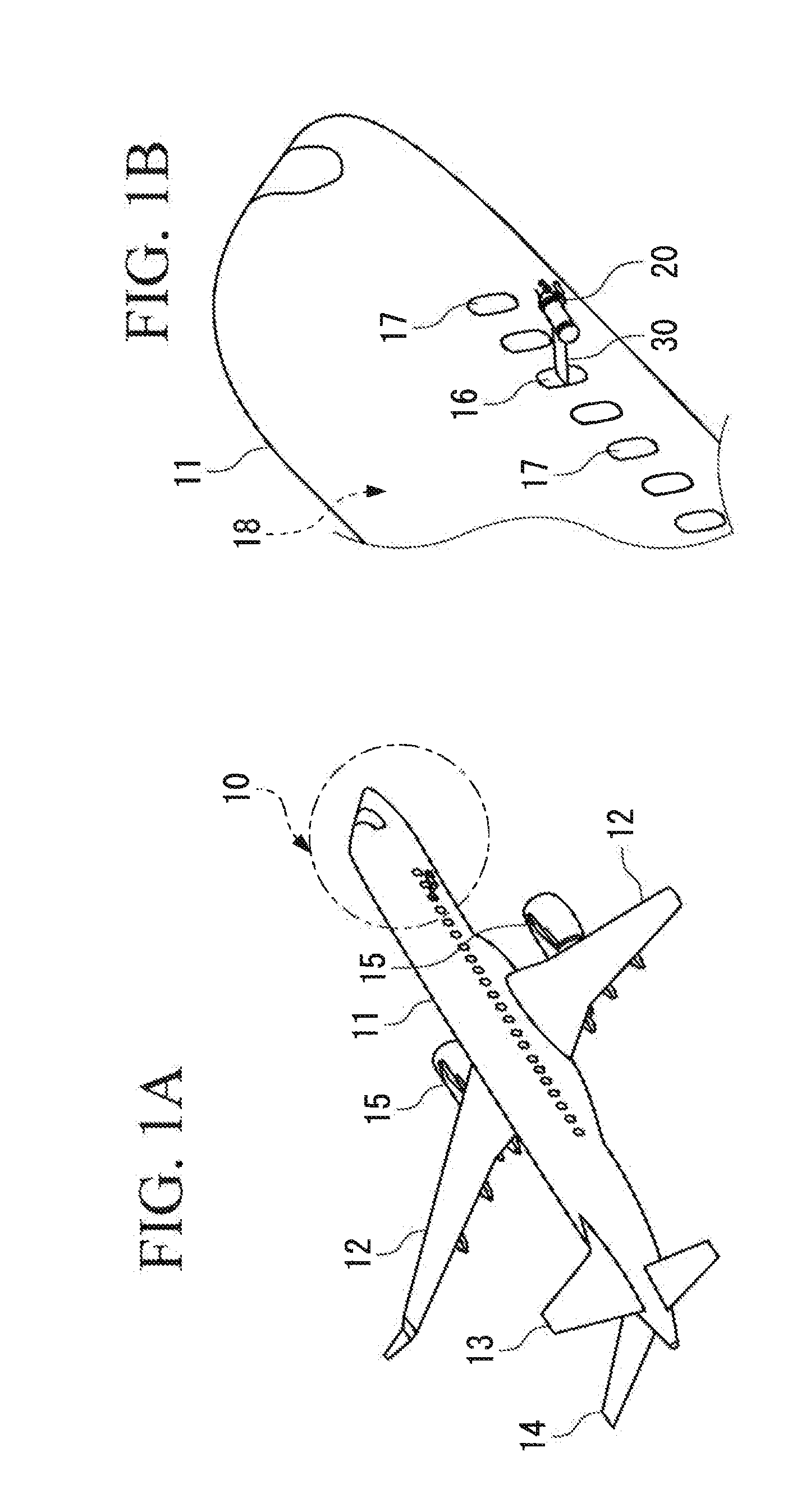
[0043]As shown in FIG. 1A, an aircraft 10 includes a fuselage 11, main wings 12 and 12 provided to the right and left of the fuselage 11, a vertical stabilizer 13, and a horizontal stabilizer 14. Engines 15 and 15 are respectively supported on the main wings 12 and 12.

[0044]In the present specification, “front” means a nose side of the aircraft 10, and “rear” means a tail side of the aircraft 10.

[0045]Also, “upper” means an upper side of an airframe of the aircraft 10, and “lower” means a lower side of the airframe of the aircraft 10.

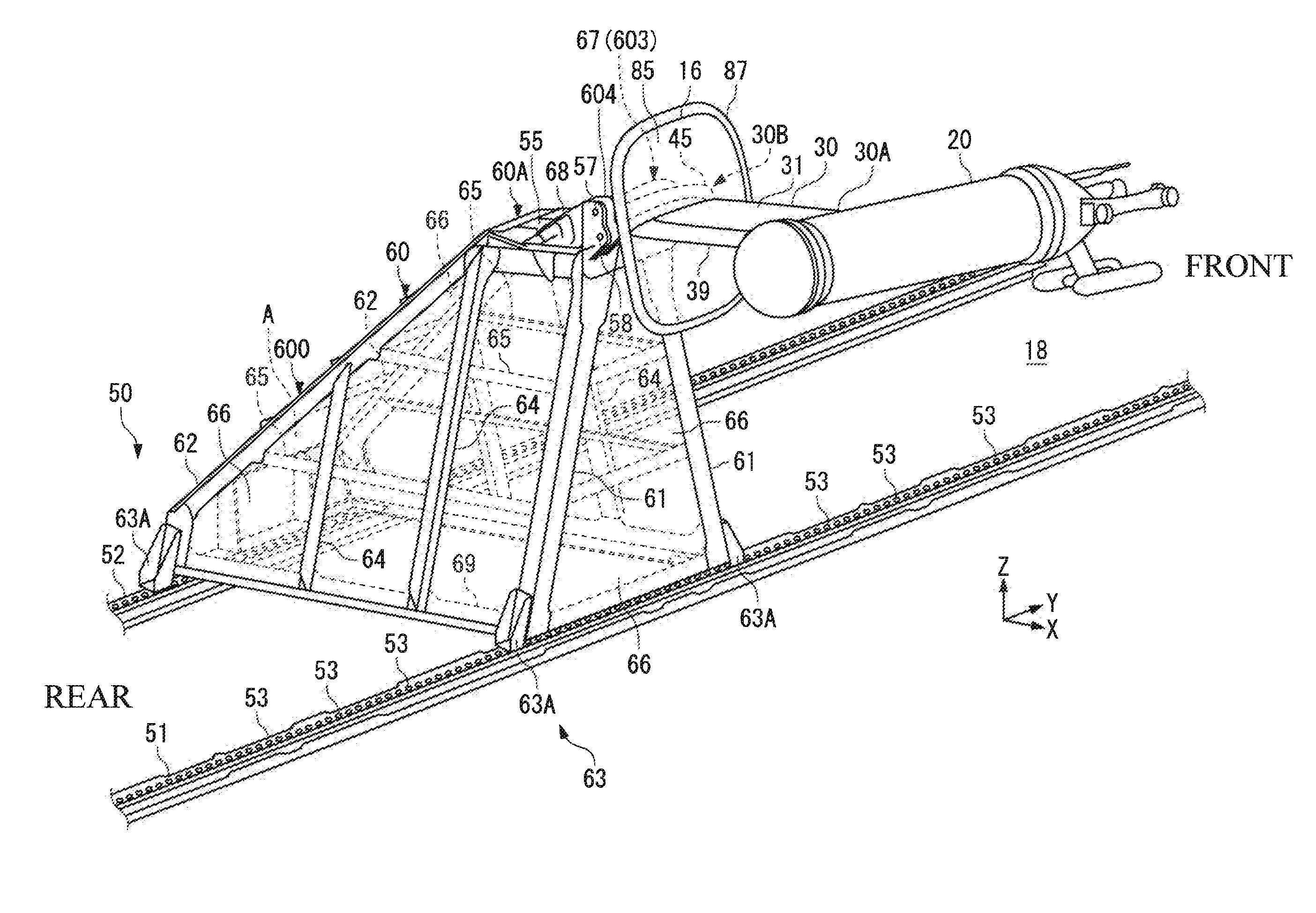
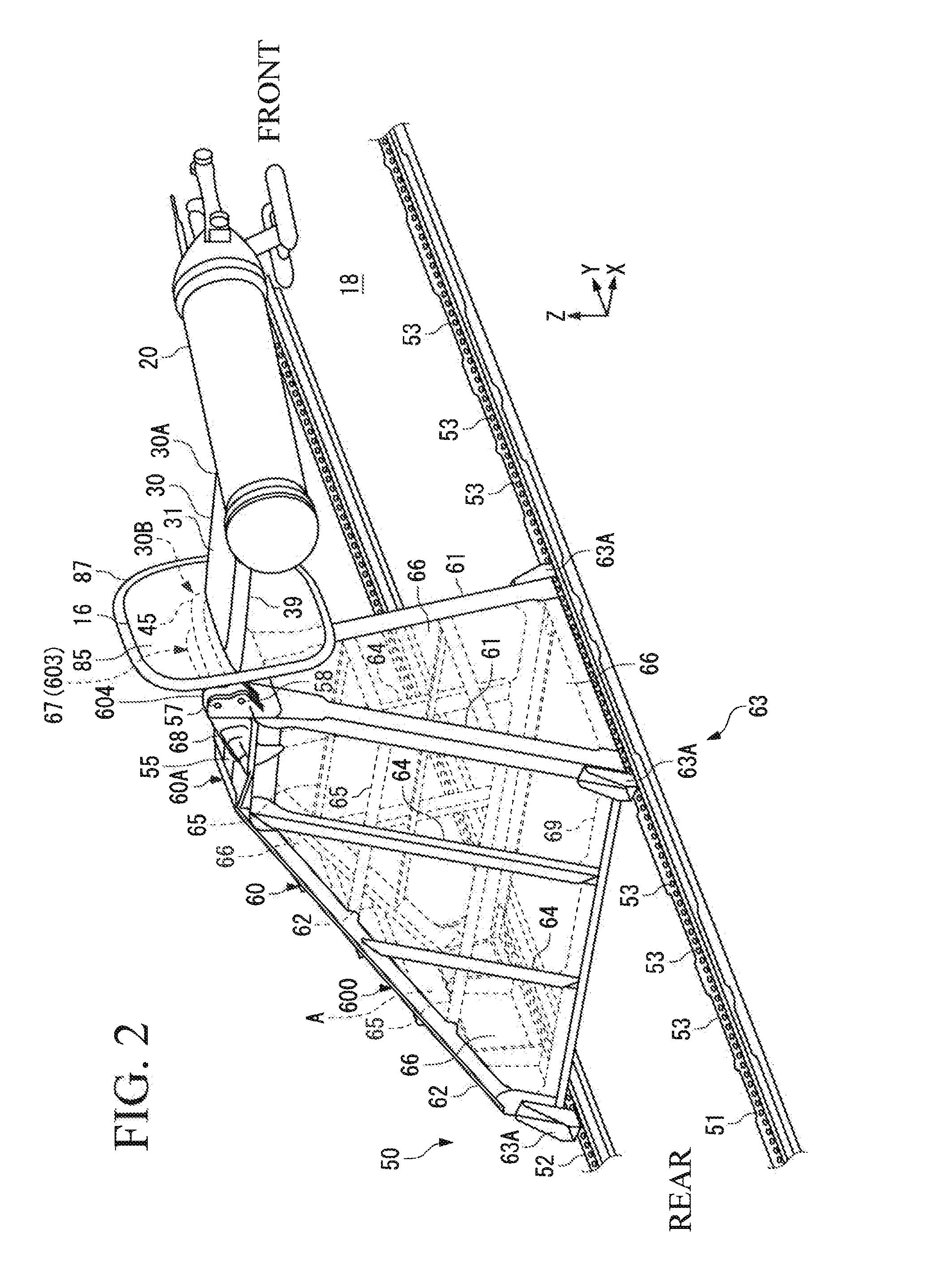
[0046]In a test flight, a measuring device 20 is attached to the airframe of the aircraft 10 as shown in FIG. 1B. The measuring device 20 is installed outside the airframe in order to obtain icing conditions on the airframe. The measuring device 20 is fixed to an arm (a penetration member) 30 that extends out of the airframe from a window 16 provided on a right side wall of the airframe.

[0047]To avoid a decrease in aerodynamic performance due to ice acc...

second embodiment

[0131]Next, a second embodiment of the present invention is described by reference to FIGS. 8 to 13.

[0132]The aircraft 10 of the present embodiment shown in FIG. 8A is provided with a pitot device (a detection device, a penetration member) 120 in a test flight. The pitot device 120 projects to the airframe outer side from the window 16 of the cabin 18.

[0133]The pitot device 120 is provided so as to obtain an accurate airspeed of the aircraft 10 in the test flight together with a trailing cone device (not shown) that trails behind the airframe from an upper end of the vertical stabilizer. The pitot device 120 is removed from the airframe when the task is finished.

[0134]The pitot device 120 and the trailing cone device are connected to an arithmetic device of an air data system (not shown).

[0135]A pitot device (not shown) that is usually used during a flight of the aircraft 10 is provided on the airframe of the aircraft 10 in addition to the pitot device used in the test flight. The p...


PUM


Abstract

An aircraft including: a penetration member that penetrates an airframe between an inside and an outside via an opening provided in the airframe; a seal that seals a gap set between an opening formation member forming the opening and the penetration member; and a retainer that presses the seal against the penetration member and the opening formation member, wherein each of the penetration member and the opening formation member includes a receiving section that receives the seal, both of the receiving sections are arranged along a direction connecting one side and the other side of the gap with the gap therebetween, and the seal is fixed to only one of the receiving section of the penetration member and the receiving section of the opening formation member.

Description

BACKGROUND OF THE INVENTION[0001]1. Field of the Invention[0002]The present invention relates to an aircraft having a structure for ensuring airtightness.[0003]2. Description of the Related Art[0004]A measuring device that measures a moisture content in the atmosphere is used for obtaining icing conditions on an airframe in a test flight of aircraft (JP2007-521463A).[0005]The measuring device can be installed outside the airframe by fixing the measuring device to an arm that is provided on the airframe and extends out of the airframe.[0006]In order to provide the arm to which the measuring device is fixed on the airframe, it is necessary for a member prepared in the airframe to receive an aerodynamic load applied to the measuring device and the arm during a flight. Since the aerodynamic load cannot be received only by a skin (an outer plate), it is difficult to achieve a configuration in which a proximal end of the arm is supported only on an outer surface side of the airframe witho...

Claims


Application Information

Patent Timeline
IPC IPC(8): F16J15/02B61D49/00B64C1/14B64D11/06B64D15/20G01F1/46G01N19/10
CPCF16J15/02B64D11/0696B64D15/20G01F1/46B61D49/00G01N19/10B64C1/14F16J15/021
Inventor GOTO, SHINGOSUGIMURA, TOSHIAKI
Owner MITSUBISHI AIRCRAFT
Why Eureka
Try Eureka