Tank for Oils or Liquids for Direct Fastening on a Fastening Surface

Inactive Publication Date: 2008-12-25
ZF FRIEDRICHSHAFEN AG
View PDF3 Cites 3 Cited by
  • Summary
  • Abstract
  • Description
  • Claims
  • Application Information

AI Technical Summary

Benefits of technology

[0006]The object of the present invention is therefore to design a tank for accommodating oils or liquids such that while having a sufficient tank volume, it can be mounted on a fastening surface in a compact manner and with reliable hold. Simple mounting, especially in poorly accessible areas, is to be supported, in particular, due to the corresponding design embodiment.
[0011]According to a possible embodiment, the tank comprises a shell-like tank part and a tank cover welded thereto and includes a filler neck for introducing the fluid in question as well as two connection pipes for integrating the tank in an oil or liquid circulation. The tank is fastened by means of at least one screw led through the tank in a duct and additional screws led through ducts on the outer circumference of the shell-like tank part. The ducts arranged on the circumference of the shell-like tank part are advantageously shortened compared to the depth of this tank part. At the same time, recesses, through which a tool can pass but the head of a screw used to fasten the tank cannot, are provided on the circumference of the tank cover, in the area of the ducts. A means ensuring captive holding, which prevents the screws introduced into the ducts from sliding out inadvertently, is thus formed. The ducts arranged on the circumference of the shell-like part of the tank are preferably shortened compared to their depth in this embodiment of the tank according to the present invention to the extent that a free space, which facilitates the mounting of the tank on the fastening surface by the screws used for fastening being able to be moved in the free space when the tank is attached to the fastening surface, is obtained between these ducts and the welded-on tank cover.
[0014]According to another advantageous variant, positioning aids may be provided on the outer surface of the tank, which is to be brought into contact with the fastening surface, in the area of the passage of the ducts for the screws. The assembly of the tank and its fastening are further simplified hereby.

Problems solved by technology

However, there is a problem, especially in automotive engineering, due to the fact that a very limited space is frequently available for the components to be mounted.
This prior art procedure for forming tanks with a possibility of fastening has not therefore proved to be very compact.

Method used


Image

  • Tank for Oils or Liquids for Direct Fastening on a Fastening Surface
  • Tank for Oils or Liquids for Direct Fastening on a Fastening Surface
  • Tank for Oils or Liquids for Direct Fastening on a Fastening Surface

Examples


Embodiment Construction

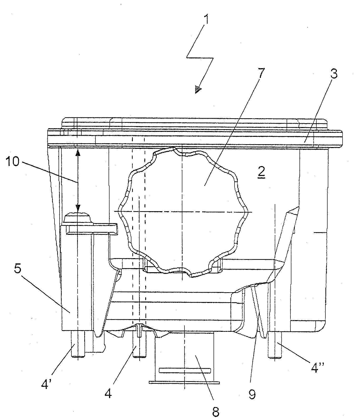
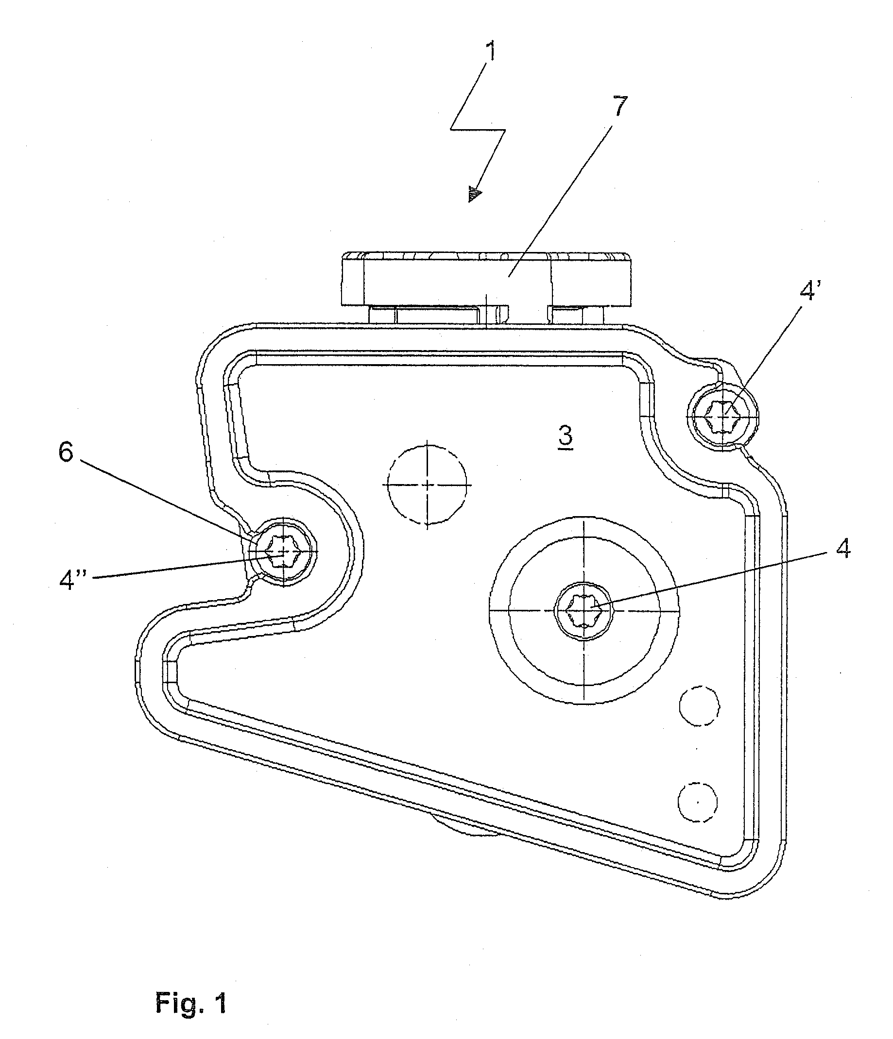
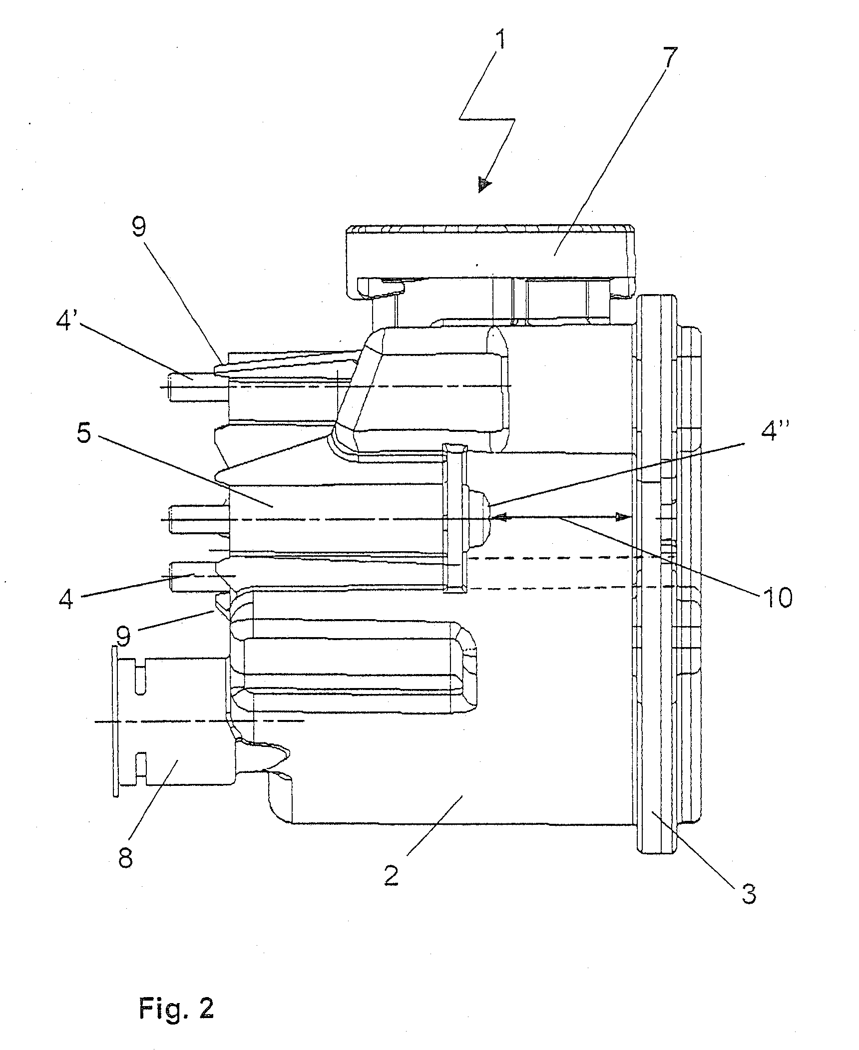
[0022]Referring to the drawings in particular, FIG. 1 shows a front view of the tank 1 according to the present invention. The tank 1 shown as an example is an oil tank for a power steering to be fastened to a motor vehicle engine. The tank 1 can be mounted on the motor vehicle engine, not shown here, by means of three screws 4, 4′, 4″ at three points. According As best seen in FIG. 5, according to the basic idea of the present invention, a screw connection is led through the tank volume, the screw 4 being used being led through a duct 5 extending through the tank 1. Two other screws 4′, 4″ act directly on the fastening surface and on a surface of the motor vehicle engine, respectively, via ducts 5 arranged on the circumference of the tank 1. As can be recognized, recesses 6, via which, for example, an electric or pneumatic screwdriver can be attached to the screws 4′, 4″ during the mounting of the tank 1, are provided in the area of these two screws 4′, 4″ on the circumference of t...


PUM


Abstract

A tank for oils or liquids designed for being fastened directly on a fastening surface. The tank can be fastened in a compact manner and with reliable hold on a fastening surface while having a sufficient tank volume. At least one fastener acting directly on the fastening surface is led through the tank volume.

Description

CROSS REFERENCE TO RELATED APPLICATIONS[0001]This application is a United States National Phase application of International Application PCT / DE 2005 / 000052 and claims the benefit of priority under 35 U.S.C. § 119 of German Patent Application DE 10 2004 002 108.2 filed Jan. 14, 2004, the entire contents of which are incorporated herein by reference.FIELD OF THE INVENTION[0002]The present invention pertains to a tank for oils or liquids designed for direct fastening on a fastening surface. Corresponding to an embodiment, it pertains specifically to an oil tank for fastening on a vehicle, preferably on a motor vehicle engine.BACKGROUND OF THE INVENTION[0003]Aside from the fuel tank, tanks for oils and / or liquids are installed at different locations in motor vehicles. The tanks are needed, for example, as an oil reservoir, in order to ensure a predetermined circulation volume for the oil in an oil circulation. They are used as oil tanks, among other things, in connection with the oil ci...

Claims


Application Information

Patent Timeline
IPC IPC(8): B60K15/00B65D1/40F01M11/06F16N19/00
CPCF16N19/00
Inventor WAGENER, KEITLINDECKERT, PETER
Owner ZF FRIEDRICHSHAFEN AG
Why Eureka
Try Eureka