Measuring straightness of an elongated rolled workpiece

Inactive Publication Date: 2009-02-19
SMS MEER +1
View PDF4 Cites 4 Cited by
  • Summary
  • Abstract
  • Description
  • Claims
  • Application Information

AI Technical Summary

Benefits of technology

[0011]In this way, even at high speeds of a continuously passing workpiece, continuous monitoring of straightness and documentation for quality management are possible, without autogenous movements of the elongated workpiece being able to distort the measured result. In addition, the measured results can be fed directly back to a rolling and in particular straightening process in a roller straightening machine.
[0012]In an apparatus according to the invention, an upstream holder and, at the spacing therefrom, in the travel direction of the workpiece, a downstream holder act on the continuously passing elongated workpiece in the measuring apparatus, and a free unsupported portion of the elongated workpiece is formed between the holders. In this way, a defined position can be set despite the leak of support for the unsupported portion of the elongated workpiece.
[0013]An advantageous embodime

Problems solved by technology

Such manual measurement takes a lot of time and, because it cannot normally be done while the process is running, leads to down time and production losses.
This laser-measurement method becomes much less effective at higher speeds, for example 10 m/s, because the actual movement of the profile or elongated workpiece, such as bouncing on the roller table or oscillations

Method used


Image

  • Measuring straightness of an elongated rolled workpiece
  • Measuring straightness of an elongated rolled workpiece
  • Measuring straightness of an elongated rolled workpiece

Examples


Example

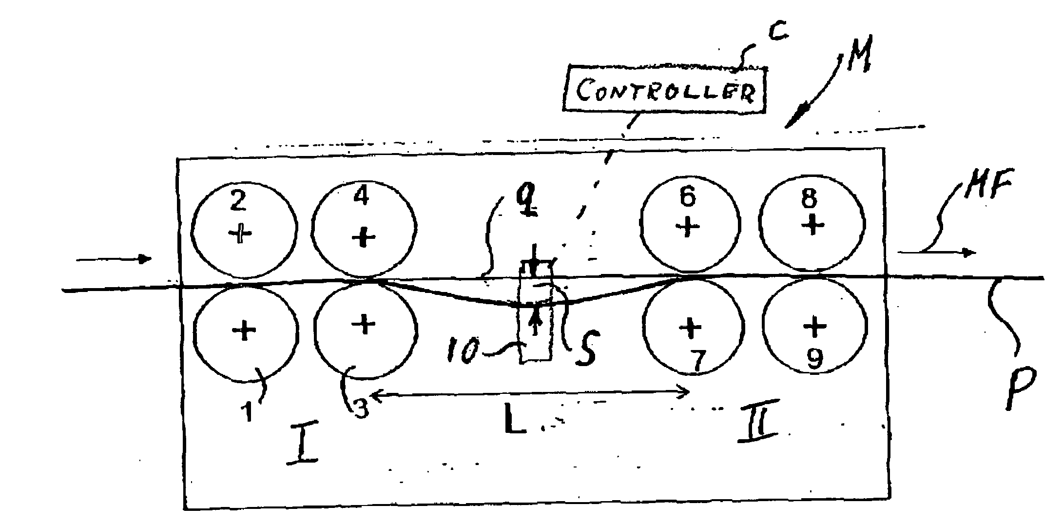
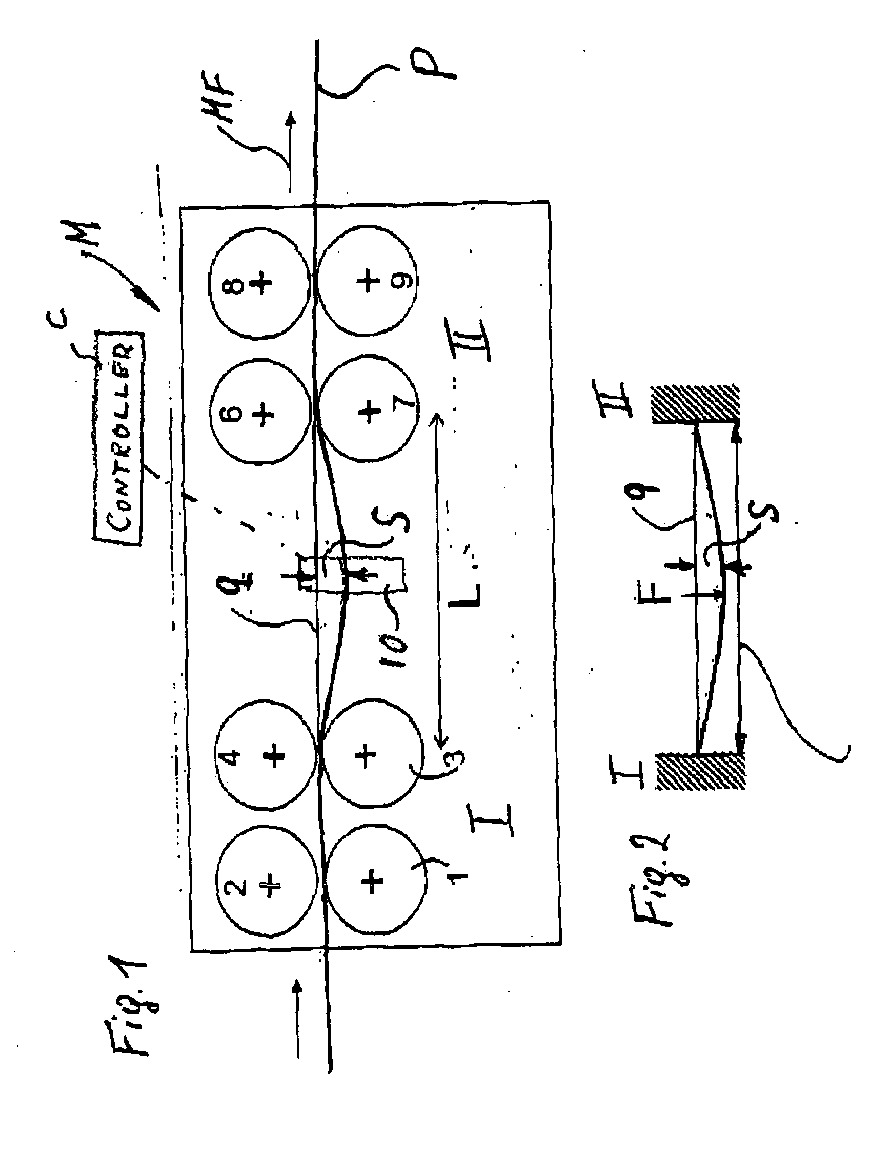
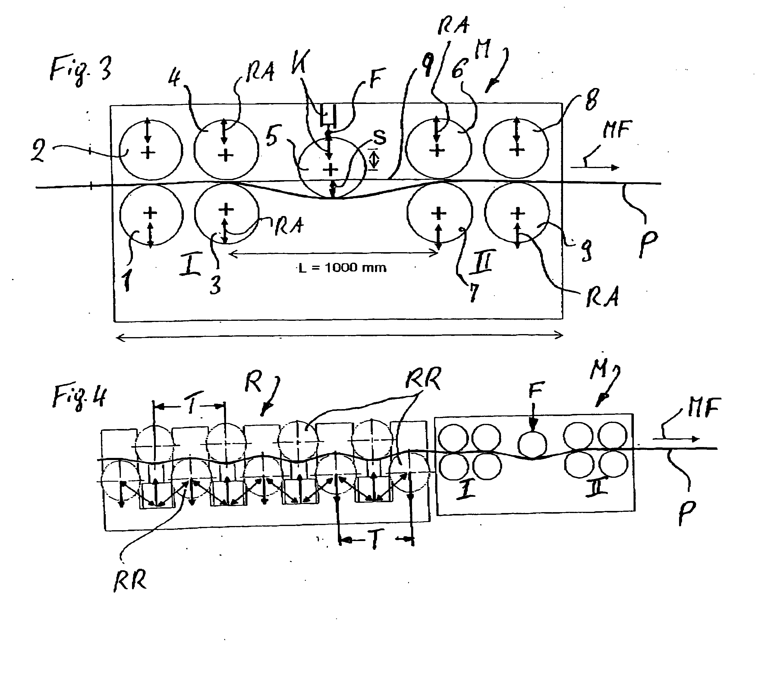
[0020]As seen in FIG. 1 a measuring apparatus M comprises two holder assemblies I and II set at a spacing from one another in a horizontal travel direction MF with two roller pairs 1, 2; 3, 4 and 5, 6; 1, 8, including upper rolls 2,4, 6 and 8 juxtaposed with respective lower rolls 1, 3, 7 and 9. The holders I and II grip an elongated workpiece P, e.g. a rolled support profile or a rail, continuously passing through the measuring apparatus M in the workpiece-travel direction MF. In passing through, the elongated workpiece F has a defined-length, unsupported portion L between the holders I and II. In this unsupported portion, the elongated workpiece P has a deflection S created by its own weight, which can be increased in a predetermined manner with elastic deformation by acting on it with a force F. A straight line g projected mathematically above the unsupported portion L makes it possible using a suitable laser-type measuring means 10 to ascertain the extent of the deflection S and...


PUM

PropertyMeasurementUnit
Weightaaaaaaaaaa
Forceaaaaaaaaaa
Lengthaaaaaaaaaa

Abstract

An elongated workpiece is treated, e.g. rolled, in a production system where treatment devices move the workpiece longitudinally in a horizontal travel direction and at a generally constant travel speed along a horizontal longitudinal path and a control computer is connected to the treatment devices. Straightness of the workpiece is measured by gripping the workpiece at a pair of longitudinally spaced supports, applying tension to a longitudinally extending horizontal portion of the workpiece between the supports, and continuously moving the workpiece in the travel direction at the travel speed with a lower surface of the portion substantially unsupported. At least periodically a vertical spacing is measured between the portion and a straight longitudinal reference line extending in the direction between the supports parallel to the workpiece at the supports. The vertical-spacing measurement are fed to the computer for use controlling the devices.

Description

FIELD OF THE INVENTION[0001]The present invention relates to a method of and apparatus for measuring straightness. More particularly this invention concerns the straightness of a continuously passing elongated workpiece, such as a rolled rail, bar, or rod, during the production thereof.BACKGROUND OF THE INVENTION[0002]It is known to determine the straightness of a profile workpiece, an I-beam for example, by placing a support bar on its flange and to measure the straight line relative to a spanned wire. Such manual measurement takes a lot of time and, because it cannot normally be done while the process is running, leads to down time and production losses.[0003]For automated measurement and determination of the straightness of rails and profiles on a continuously passing workpiece, it is known from the prior art to utilise laser measuring devices and / or methods. In doing so, the rail is moved across a roller bed at approximately 1 m / s and the spacing between the laser head and the r...

Claims


Application Information

Patent Timeline
IPC IPC(8): B21B37/28G01B11/24B21B37/00
CPCB21B38/00G01B13/16G01B11/24G01B11/16
Inventor DAUBE, THOMASNERZAK, THOMAS
Owner SMS MEER
Why Eureka
Try Eureka