Biophotonic materials and uses thereof

a biophotonic material and material technology, applied in the field of biophotonic materials for phototherapy, can solve the problems of low therapeutic efficacy of existing regimens, inability to achieve the desired effect, so as to promote wound healing, prevent or treat scarring, and promote wound healing

Active Publication Date: 2016-02-04
FLE INT SRL
View PDF6 Cites 9 Cited by
  • Summary
  • Abstract
  • Description
  • Claims
  • Application Information

AI Technical Summary

Benefits of technology

[0012]From another aspect, there is provided a topical biophotonic material comprising: a cohesive matrix, and at least one chromophore which can absorb and emit light from within the biophotonic material, wherein the topical biophotonic material is a mask or a dressing. In certain embodiments, the mask and / or the dressing has a pre-formed configuration. In certain embodiments, the mask and / or the dressing is elastic. In certain embodiments, the mask and / or the dressing is rigid.
[0044]From another aspect, there is provided a method for preventing or treating scarring comprising: placing a topical biophotonic material which is a membrane over or within a wound, wherein the topical biophotonic material comprises at least one chromophore and a cohesive matrix; and illuminating said biophotonic material with light having a wavelength that overlaps with an absorption spectrum of the at least one chromophore; wherein said topical biophotonic material emits fluorescence at a wavelength and intensity that promotes wound healing.

Problems solved by technology

Such regimens, however, are often associated with undesired side-effects, including systemic or localized toxicity to the patient or damage to non-targeted tissue.
Moreover, such existing regimens often demonstrate low therapeutic efficacy due to, for example, the poor selectivity of the photosensitive agents into the target tissues.

Method used


Image

  • Biophotonic materials and uses thereof
  • Biophotonic materials and uses thereof
  • Biophotonic materials and uses thereof

Examples


example 1

Preparation of an Exemplary Cohesive Biophotonic Material

[0232]A cohesive biophotonic material was prepared according to an embodiment of the present disclosure and as summarized in Table 1.

TABLE 1Composition of a cohesive biophotonic material according to an embodiment of the present disclosure.Ingredients% in composition (wt / wt)Water60-95Glycerine 5-15Propylene Glycol2-6Sodium hyaluronate 2-8Urea peroxide1-5Glucosamine sulfate0.5-4  Carbopol0.1-2  First Chromophore0.001-0.01 Second chromophore0.001-0.01 

[0233]Phase A was prepared by mixing water, eosin Y, rose bengal and glucosamine sulphate. Phase B (water, glycerine, propylene glycol, urea peroxide, carbopol) was then added to Phase A, and mixed until a light viscous liquid was obtained. Phase C (sodium hyaluronate) was then added to the mixture, and mixed until a homogenous thick cohesive gel was obtained. This cohesive homogenous gel was spread onto a flat surface, covered with an aluminum sheet and allowed to dry for 24 hours...

example 2

Angiogenic Potential of a Biophotonic Composition

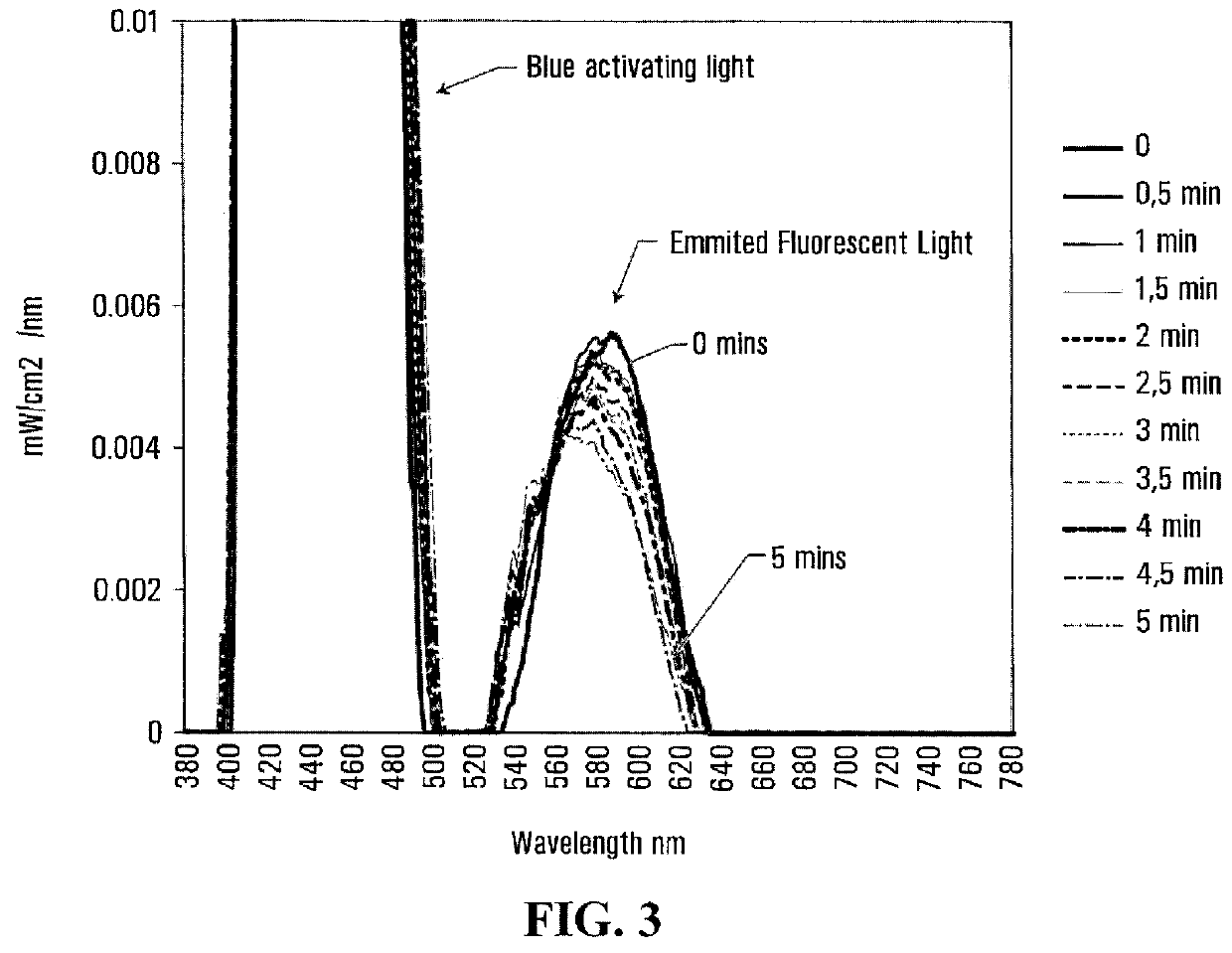
[0234]The angiogenic potential of a biophotonic composition was evaluated using a human skin model containing fibroblasts and keratinocytes. The composition was a transparent gel comprising fluorescent chromophores, eosin Y and erythrosine. Briefly, the biophotonic composition was placed on top of the human skin model such that they were separated by a nylon mesh of 20 micron pore size. The composition was then irradiated with blue light (‘activating light’) for 5 minutes at a distance of 10 cm from the light source. The activating light consisted of light emitted from an LED lamp having an average peak wavelength of about 400-470 nm and a power density of about 30-150 mW / cm2. At a 10 cm distance from the LEDs, the activating light had a power at the peak wavelength of about 2-3 mW / cm2 / nm (about 2.5 mW / cm2 / nm), an average power of about 55-65 mW / cm2, and a fluence in 5 minutes of irradiation of about 15-25 J / cm2 (about 16-20 J / cm2). U...

example 3

Protein Secretion and Gene Expression Profiles of a Biophotonic Composition

[0236]Wounded and unwounded 3D human skin models (EpiDermFT™, MatTek Corporation) were used to assess the potential of a composition to trigger distinct protein secretion and gene expression profiles. The biophotonic composition comprised fluorescent chromophores eosin Y and erythrosine. The composition was placed on top of wounded and unwounded 3D human skin models cultured under different conditions (with growth factors, 50% growth factors and no growth factors). The skin models and the composition were separated by a nylon mesh of 20 micron pore size. Each skin model-composition combination was then irradiated with blue light (‘activating light’) for 2 minutes by light having a profile similar to that described in Example 2. The fluorescence emission is shown in FIG. 4. The controls consisted of 3D skin models not illuminated with light.

[0237]Gene expression and protein secretion profiles were measured 24 ...


PUM

PropertyMeasurementUnit
thicknessaaaaaaaaaa
thicknessaaaaaaaaaa
thicknessaaaaaaaaaa

Abstract

The present disclosure provides topical biophotonic materials and methods useful in phototherapy. In particular, the topical biophotonic materials of the present disclosure include a cohesive matrix, and at least chromophore which can absorb and emit light from within the topical biphotonic material, wherein the topical biophotonic material is elastic. The topical biophotonic materials and the methods of the present disclosure are useful for promoting wound healing and skin rejuvenation, as well as treating acne and various other skin disorders.

Description

FIELD OF THE INVENTION[0001]The present disclosure generally relates to biophotonic materials for phototherapy.BACKGROUND OF THE DISCLOSURE[0002]Phototherapy has recently been recognized as having wide range of applications in both the medical and cosmetic fields including use in surgery, therapy and diagnostics. For example, phototherapy has been used to treat cancers and tumors with lessened invasiveness, to disinfect target sites as an antimicrobial treatment, to promote wound healing, and for facial skin rejuvenation.[0003]Photodynamic therapy is a type of phototherapy involving the application of a photosensitive agent to target tissue then exposing the target tissue to a light source after a determined period of time during which the photosensitizer is absorbed by the target tissue. Such regimens, however, are often associated with undesired side-effects, including systemic or localized toxicity to the patient or damage to non-targeted tissue. Moreover, such existing regimens ...

Claims


Application Information

Patent Timeline
Patent Type & Authority Applications(United States)
IPC IPC(8): A61N5/06A61K41/00
CPCA61K41/0057A61N2005/0658A61N5/0616A61N5/062A61K8/498A61Q19/00A61Q19/08A61K8/042A61K8/0212A61K8/0216A61K2800/434A61N2005/0662A61P1/02A61P17/00A61P17/02A61P17/04A61P17/06A61P17/10A61K8/02A61K9/00A61K41/00A61L15/42A61N5/06A61K47/32A61K8/735A61K47/36A61K2800/81A61M11/00
Inventor LOUPIS, NIKOLAOSPIERGALLINI, REMIGIODESROSIERS, ERIC
Owner FLE INT SRL
Why Eureka
Try Eureka