
Video quality evaluation method based on 3D wavelet transform

a video quality and wavelet transform technology, applied in the field of video signal processing technology, can solve the problems of reducing video quality, time-consuming and difficult to be integrated into the video system, and limited understanding of the processing methods of human eye when viewing video information at present, so as to achieve the effect of improving relativity

Inactive Publication Date: 2016-01-28
NINGBO UNIV
View PDF7 Cites 4 Cited by
  • Summary
  • Abstract
  • Description
  • Claims
  • Application Information

AI Technical Summary

Benefits of technology

The present invention provides a video quality evaluation method based on 3D wavelet transform. This method effectively improves the accuracy of objective video quality evaluation and the relativity between the objective quality evaluation result and the subjective quality judged by human eyes. By using 3D wavelet transform, the video time-domain information is described, which is difficult to be described using other methods. This improves the accuracy of video quality evaluation and helps to make it more reliable.

Problems solved by technology

Because of a series of uncontrollable factors, video information will be inevitably distorted in video acquisition, compression, transmission, decoding and display stages, resulting in decrease of video quality.
However, subjective quality evaluation requires scoring by observer, which is time-consuming and not easy to be integrated in the video system.
Although time-domain information of video sequences are described from different angles according to the above methods, understanding of processing methods of human eye when viewing video information is limited at present.
Therefore, time-domain information description according to the above methods is limited, which means it is difficult to evaluate the video time-domain quality, and will eventually lead to poor consistency of objective evaluation results with subjective evaluation visual results.

Method used


Image

  • Video quality evaluation method based on 3D wavelet transform
  • Video quality evaluation method based on 3D wavelet transform
  • Video quality evaluation method based on 3D wavelet transform

Examples


Embodiment Construction

[0044]Referring to the drawings and a preferred embodiment, the present invention is further illustrated.

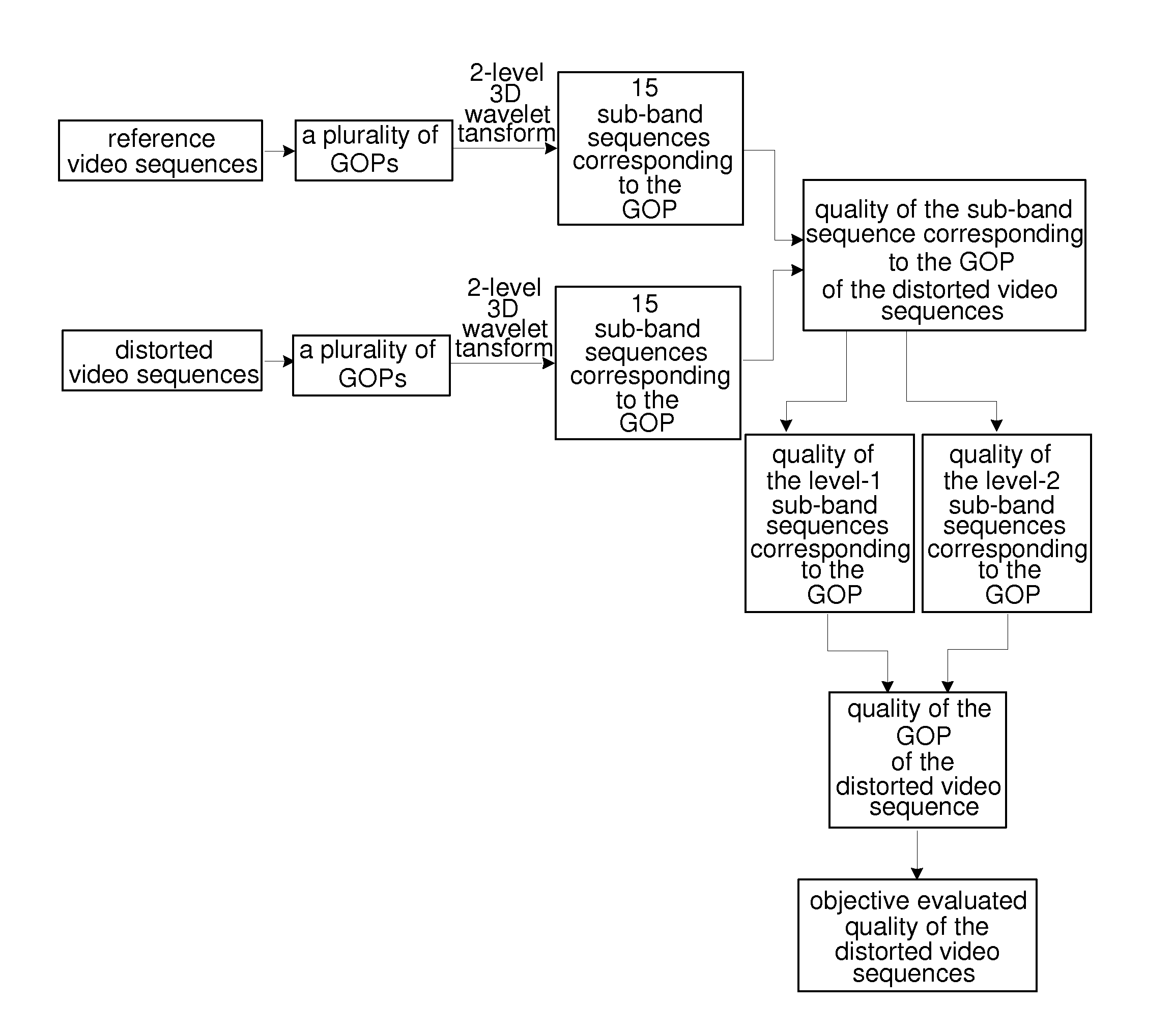
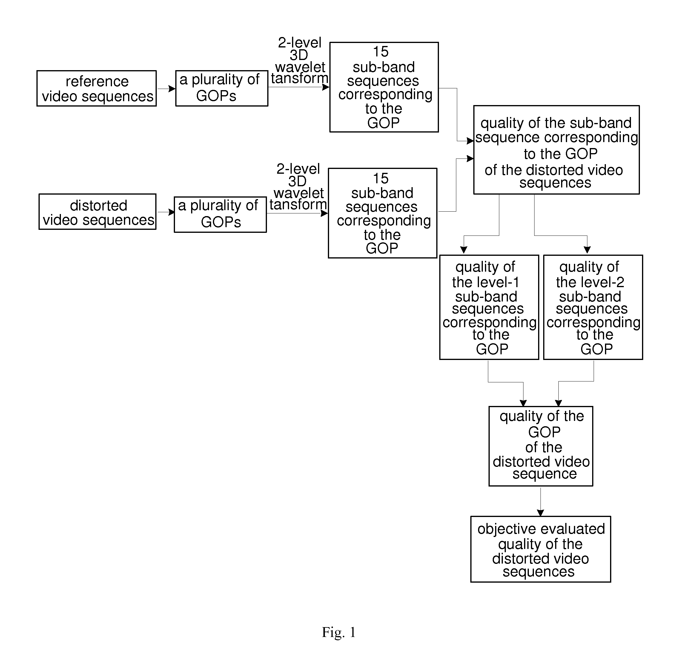
[0045]Referring to FIG. 1 of the drawings, a video quality evaluation method based on 3D wavelet transform is illustrated, comprising steps of:

[0046]a) marking an original undistorted reference video sequence as Vref, marking a distorted video sequence as Vdis, wherein the Vref and the Vdis both comprise Nfr frames of images, wherein Nfr≧2n, n is a positive integer, and nε[3,5], wherein n=5 in the preferred embodiment;

[0047]b) regarding 2n frames of images as a group of picture (GOP for short), respectively dividing the Vref and the Vdis into nGoF GOPs, marking a No. i GOP in the Vref as Grefi, marking a No. i GOP in the Vdis as Gdisi, wherein

nGoF=⌊Nfr2⌋,

the symbol └┘ means down-rounding, and 1≦i≦nGoF;

[0048]wherein in the preferred embodiment, n=5, therefore, each of the GOPs comprises 32 frames of images; in practice, if quantities of the frames of images of the Vref and the Vdi...


PUM


Abstract

A video quality evaluation method based on 3D wavelet transform utilizes 3D wavelet transform in the video quality evaluation, for transforming the group of pictures (GOP for short) of the video. By splitting the video sequence on a time axis, time-domain information of the GOPs is described, which to a certain extent solves a problem that the video time-domain information is difficult to be described, and effectively improves accuracy of objective video quality evaluation, so as to effectively improve relativity between the objective quality evaluation result and the subjective quality judged by the human eyes. For time-domain relativity between the GOPs, the method weighs the quality of the GOPs according to the motion intensity and the brightness, in such a manner that the method is able to better meet human visual characteristics.

Description

CROSS REFERENCE OF RELATED APPLICATION[0001]The present invention claims priority under 35 U.S.C. 119(a-d) to CN 201410360953.9, filed Jul. 25, 2014.BACKGROUND OF THE PRESENT INVENTION[0002]1. Field of Invention[0003]The present invention relates to a video signal processing technology, and more particularly to a video quality evaluation method based on 3-dimensional (3D for short) wavelet transform.[0004]2. Description of Related Arts[0005]With the rapid development of video coding technology and display technology, different kinds of video systems are applied more and more widely, and gradually become the research focus of the field of information processing. Because of a series of uncontrollable factors, video information will be inevitably distorted in video acquisition, compression, transmission, decoding and display stages, resulting in decrease of video quality. Therefore, how to accurately measure the video quality is the key for the development of video system. Video qualit...

Claims


Application Information

Patent Timeline
Patent Type & Authority Applications(United States)
IPC IPC(8): H04N17/00
CPCG06T2207/30168H04N17/00G06T7/0002G06T2207/10016G06T2207/20064H04N17/004
Inventor JIANG, GANGYISONG, YANGLIU, SHANSHANZHENG, KAIHUIJIN, XIN
Owner NINGBO UNIV
Learn More