
Method for manufacturing organic light emitting element, and organic light emitting element

a technology of organic light emitting elements and manufacturing methods, which is applied in the direction of luminescent compositions, chemistry apparatuses and processes, thermoelectric devices, etc., can solve the problems of increasing the resistance of the resulting layer on the sheet, and the inability of transparent metal electrodes to be suitable, so as to improve the luminescence efficiency and durability.

Active Publication Date: 2016-01-21
MERCK PATENT GMBH
View PDF2 Cites 17 Cited by
  • Summary
  • Abstract
  • Description
  • Claims
  • Application Information

AI Technical Summary

Benefits of technology

The patent text describes a method for making a smoothing layer with high clarity and a low refractive index. The method involves using metal oxide nanoparticles with a specific size and refractive index. The nanoparticles are dispersed in a solvent and applied to a substrate to form a smooth layer. The refractive index of the layer is controlled by the amount of nanoparticles used, with lower refractive indices achieved by using larger nanoparticles. The layer also has low flex cracking resistance, so a higher content of nanoparticles is needed to improve its strength. The use of titanium dioxide nanoparticles with specific properties and a controlled size helps to achieve the desired optical properties and durability of the smoothing layer.

Problems solved by technology

These islands cause technical difficulties in formation of a thin conductive electrode layer and increase the sheet resistance of the resulting layer.
In consequence, the resulting transparent metal electrode is not suitable.

Method used


Image

  • Method for manufacturing organic light emitting element, and organic light emitting element
  • Method for manufacturing organic light emitting element, and organic light emitting element
  • Method for manufacturing organic light emitting element, and organic light emitting element

Examples


examples

Preparation of Sample of Internal Light Extracting Layer

(1) PREPARATION OF TRANSPARENT SUBSTRATE

[0352]In accordance with Example 1 of Japanese Patent Application Laid-Open Publication No. 2012-116101, a gas barrier layer was formed on a transparent PET substrate (thickness: 125 μm).

[0353]Specifically, an UV-curable organic / inorganic hybrid hard coat material OPSTAR Z7535 made by JSR Corporation was applied to one of easy-to-bond surfaces of a polyester film (made by Teijin DuPont Films Japan Limited, ultra-low-heat shrinkable PET Q83, width: 500 mm, thickness: 125 μm) into a coated layer with a dry thickness of 4 μm. Then, the layer was dried and cured at 80° C. for three minutes, with a high pressure mercury lamp at 1.0 J / cm2 in under an air atmosphere, to form a bleed-out blocking layer.

[0354]In the subsequent step, an UV-curable organic / inorganic hybrid hard coat material OPSTAR Z7501 made by JSR Corporation was applied to the other surface of the resin substrate into a coated la...


PUM

PropertyMeasurementUnit
particle sizeaaaaaaaaaa
refractive indexaaaaaaaaaa

Abstract

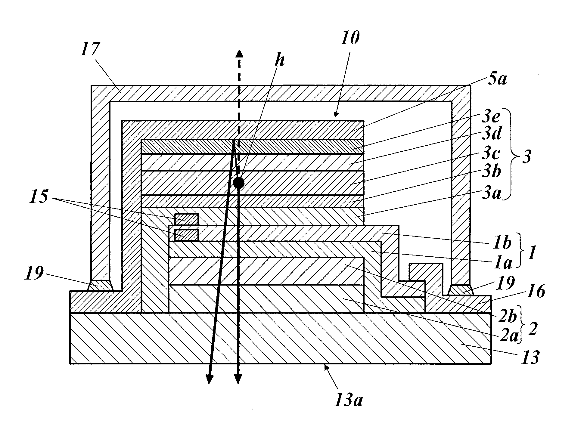
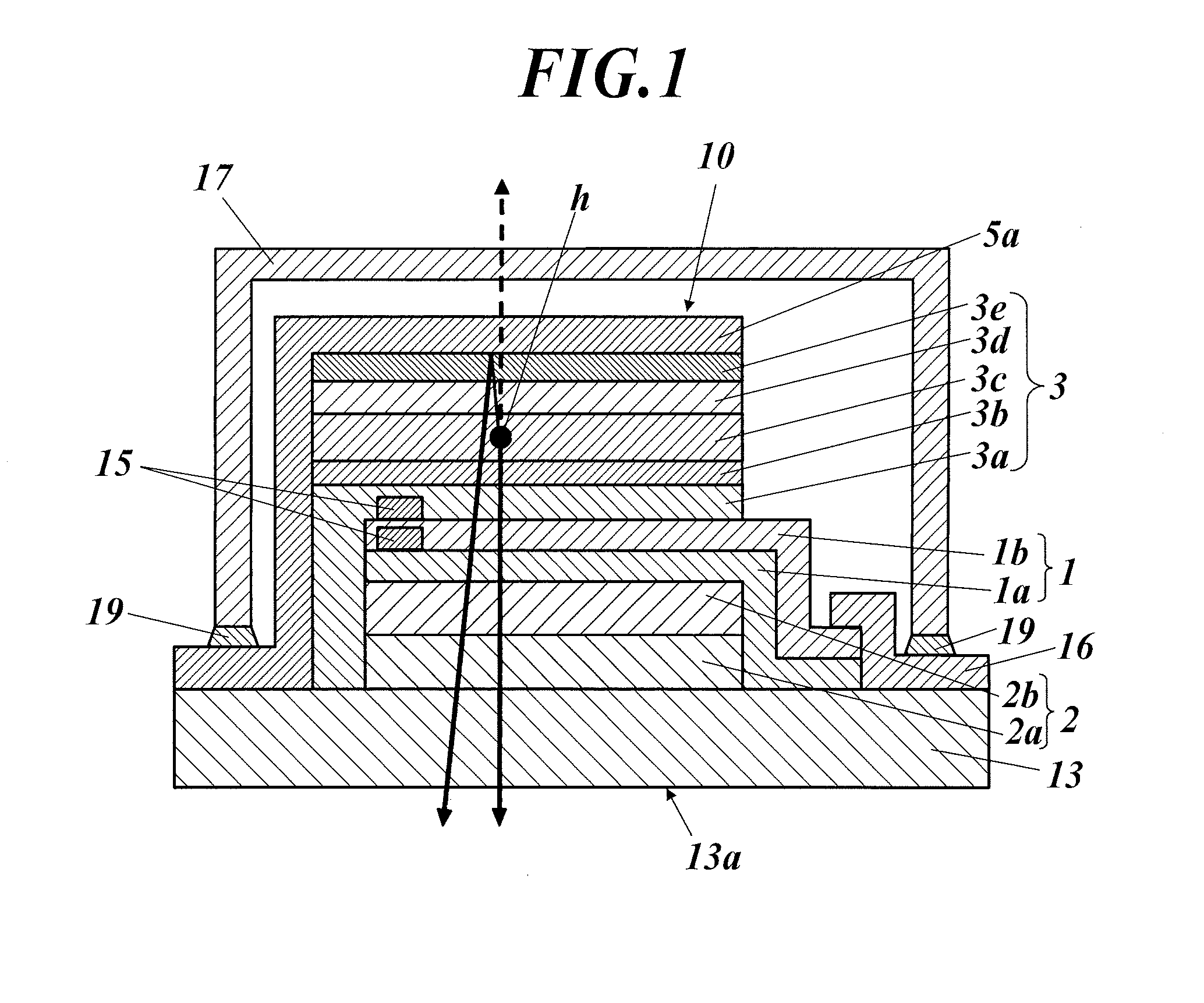
A method of manufacturing an organic light emitting element equipped with a transparent substrate, an internal light extracting layer, and a transparent metal electrode includes: forming the internal light extracting layer on the transparent substrate, and forming the transparent metal electrode on the internal light extracting layer. The step of forming the internal light extracting layer includes: applying a coating solution onto the transparent substrate into a predetermined pattern, the coating solution containing a light scattering particle having an average particle size of 0.2 μm or more and less than 1 μm and a refractive index of 1.7 or more and less than 3.0 and a hydroxy-containing solvent, and drying the applied patterned coating solution through irradiation with infrared light having a proportion of 5% or less of a spectral radiance at a wavelength of 5.8 μm to a spectral radiance at a wavelength of 3.0 μm.

Description

CROSS REFERENCE TO RELATED APPLICATIONS[0001]This is the U.S. national stage of application No. PCT / JP2014 / 054015, filed on Feb. 20, 2014. Priority under 35 U.S.C. §119(a) and 35 U.S.C. §365(b) is claimed from Japanese Application No. 2013-033199 filed on Feb. 22, 2013, the disclosure of which is also incorporated herein by reference.TECHNICAL FIELD[0002]The present invention relates to methods for manufacturing organic light emitting elements, and organic light emitting elements, and in particular, relates to a method for manufacturing organic light emitting elements which is suitably used in mass production of organic light emitting elements having enhanced luminescence efficiency and durability, and organic light emitting elements manufactured by the method.BACKGROUND ART[0003]Organic light emitting elements have come to attention as thin luminous materials.[0004]Organic light emitting elements utilizing electroluminescence (EL) of organic materials (the so-called organic EL elem...

Claims


Application Information

Patent Timeline
Patent Type & Authority Applications(United States)
IPC IPC(8): H01L51/52H01L51/56
CPCH01L51/56H01L51/5268C09K11/06C09K2211/185H10K50/854H10K50/858H10K2102/331H10K71/40H10K2101/20H10K71/00H10K2101/00
Inventor KUROKI, TAKAAKI
Owner MERCK PATENT GMBH
Learn More