
Optoelectronic apparatus and fabrication method of the same

Active Publication Date: 2016-01-21
FUNDACIO INST DE CIENCIES FOT NIQUES
View PDF18 Cites 47 Cited by
  • Summary
  • Abstract
  • Description
  • Claims
  • Application Information

AI Technical Summary

Benefits of technology

The invention is an optoelectronic device and a method for making it that has improved responsivity in low dark current levels and can pick up a wider range of colors due to the use of a 2-dimensional semiconductor transport layer and a photosensitizing layer with colloidal quantum dots.

Problems solved by technology

This dark current level requirement further affects the sensitivity and the shot-noise limit of the apparatus.
However, this technology presents a limited spectral coverage, determined by the bandgap of the MoS2.

Method used


Image

  • Optoelectronic apparatus and fabrication method of the same
  • Optoelectronic apparatus and fabrication method of the same
  • Optoelectronic apparatus and fabrication method of the same

Examples


Embodiment Construction

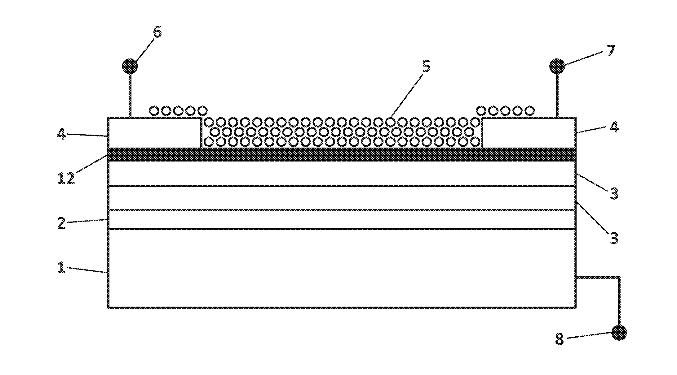
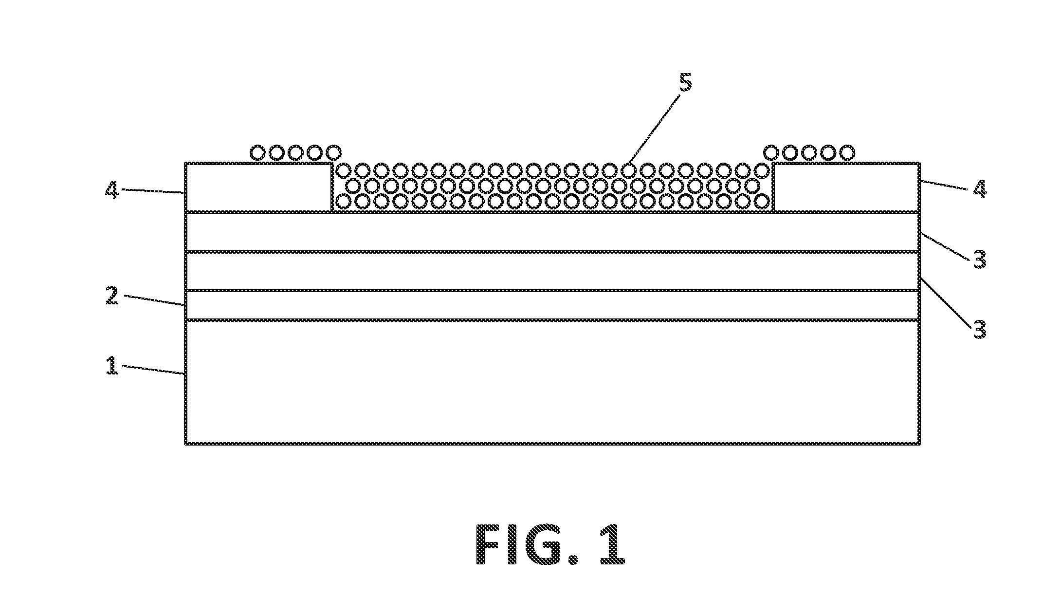
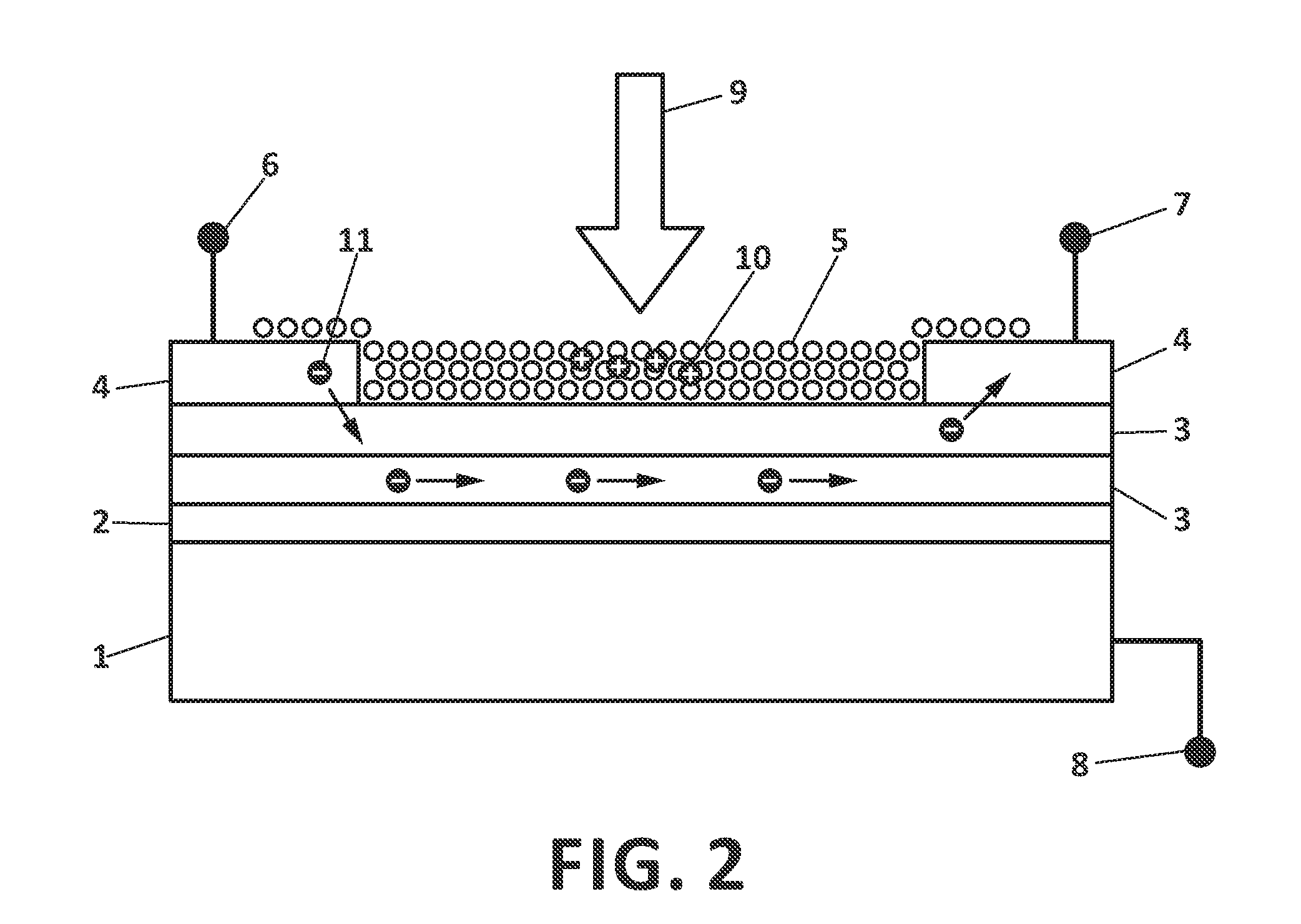
[0023]The matters defined in this detailed description are provided to assist in a comprehensive understanding of the invention. Accordingly, those of ordinary skill in the art will recognize that variation changes and modifications of the embodiments described herein can be made without departing from the scope and spirit of the invention. In particular, the preferred embodiments of the invention are described for an optoelectronic apparatus based on a MoS2 transport layer sensitized with PbS quantum dots. Nevertheless, the description of the photonic structures and of their underlying mechanism can be generally applied to other materials.

[0024]Note that in this text, the term “comprises” and its derivations (such as “comprising”, etc.) should not be understood in an excluding sense, that is, these terms should not be interpreted as excluding the possibility that what is described and defined may include further elements, steps, etc.

[0025]FIG. 1 shows a cross-sectional view of a pr...


PUM


Abstract

An optoelectronic apparatus, such as a photodetector apparatus comprising a substrate (1), a dielectric layer (2), a transport layer, and a photosensitizing layer (5). The transport layer comprises at least a 2-dimensional semiconductor layer (3), such as MoS2, and the photosensitizing layer (5) comprises colloidal quantum dots. Enhanced responsivity and extended spectral coverage are achieved with the disclosed structures.

Description

CROSS-REFERENCE TO RELATED APPLICATIONS[0001]Priority is hereby claimed under 35 USC §119 to co-pending European patent application Serial No. 14177172.5, filed 15 Jul. 2014, which is incorporated herein by reference.FIELD OF THE INVENTION[0002]The present invention has its application within the optoelectronics sector and, especially, in the industrial area engaged in providing optoelectronic platforms with enhanced photoconductive gain.BACKGROUND OF THE INVENTIONRelated Art[0003]Many optoelectronic applications, such as photodetectors and photovoltaic cells, rely on the generation of an electric current under incidence of incoming light upon the device. Light absorption at an active layer triggers the separation of electron-hole pairs, with free electrons circulating through a transport layer driven by an electric field applied by electrodes. In order to provide an efficient conversion under diverse conditions and wavelength regimes, many optoelectronic platforms have been propose...

Claims


Application Information

Patent Timeline
IPC IPC(8): H01L31/113H01L31/0336H01L31/0352H01L31/18
CPCH01L31/1136H01L31/0336H01L31/18H01L31/035272H01L31/035218H01L31/101
Inventor KONSTANTATOS, GERASIMOSKOPPENS, FRANKKUFER, DOMINIKNIKITSKIY, IVAN
Owner FUNDACIO INST DE CIENCIES FOT NIQUES
Learn More