
Systems and methods for coronary imaging

a computed tomography and imaging system technology, applied in tomography, image enhancement, instruments, etc., can solve the problems of clinician workflow problems, difficult for clinicians to perform accurate diagnostic interpretation, and motion of objects being imaged,

Active Publication Date: 2016-01-14
GENERAL ELECTRIC CO
View PDF2 Cites 17 Cited by
  • Summary
  • Abstract
  • Description
  • Claims
  • Application Information

AI Technical Summary

Benefits of technology

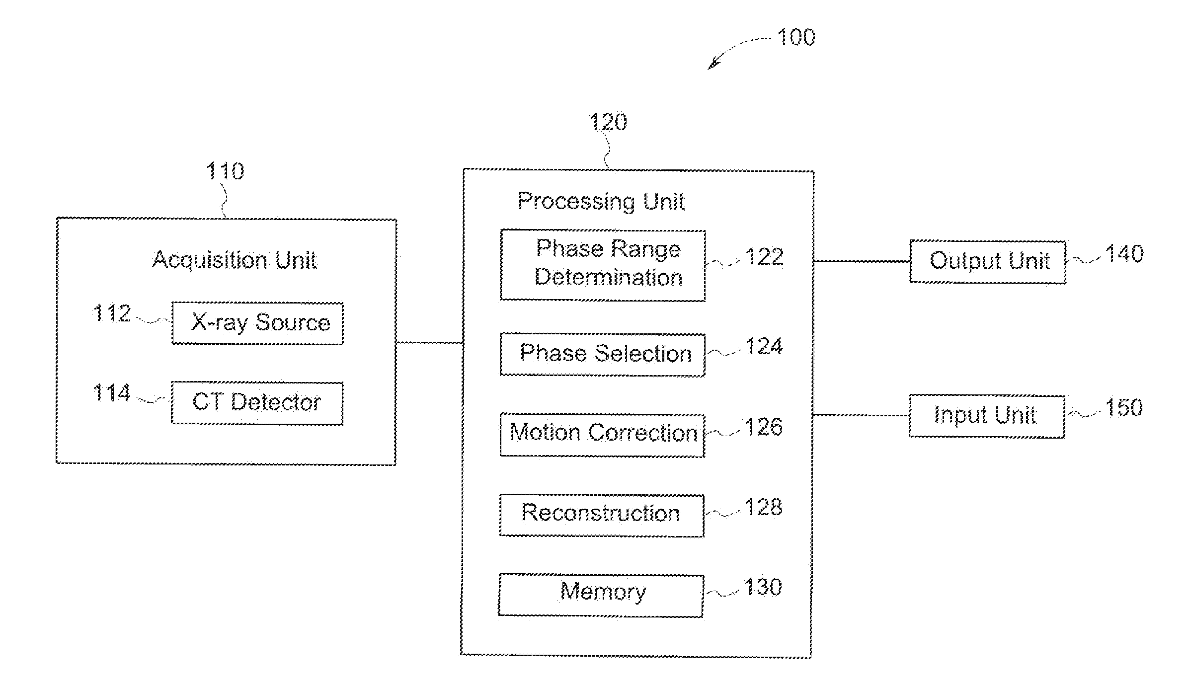
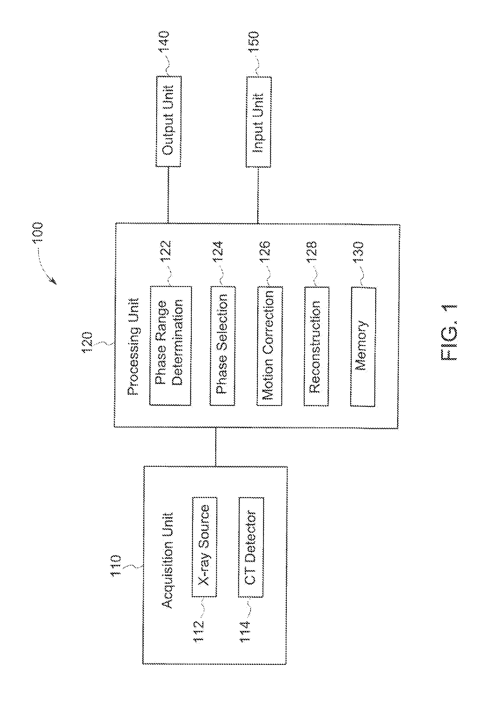
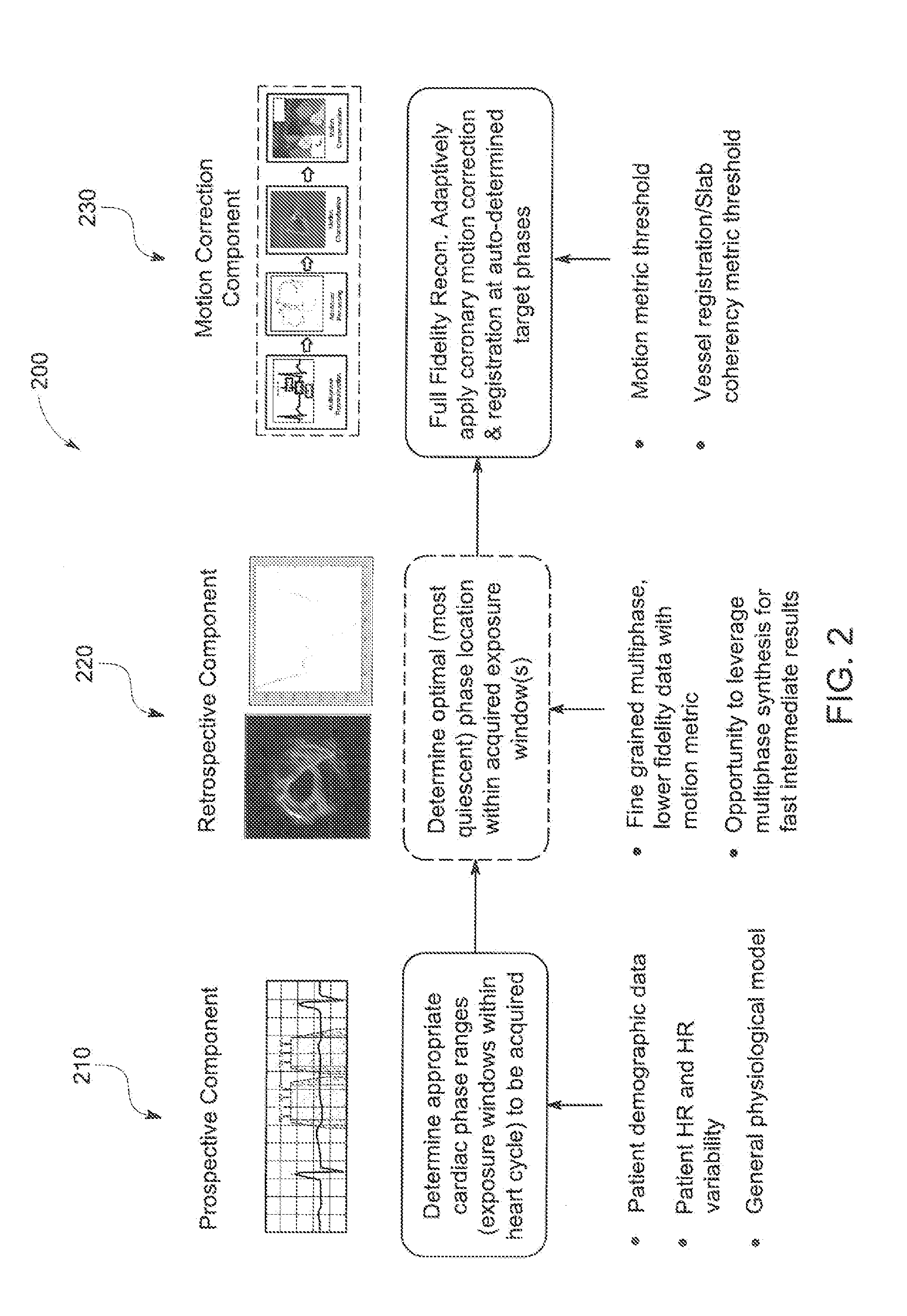
The patent describes a method and system for improving the quality of X-ray CT images of a patient's heart. The method involves determining the phases of the cardiac cycle and generating intermediate images for each phase. These images are then selected based on their quality to obtain the final image for diagnostic use. The system includes an X-ray source and a CT detector and is designed to improve the accuracy and reliability of heart imaging.

Problems solved by technology

Motion of an object being imaged may present challenges to CT imaging.
For example, cardiac motion may blur the coronary arteries in coronary CT angiography images, making it difficult for clinicians to perform an accurate diagnostic interpretation.
Reconstructing a cardiac volume at a phase of the cardiac cycle with the least motion may provide cardiologists with a more accurate representation of the coronaries; however, generating images at a multitude of cardiac phases and evaluating each of them to find the optimal phase creates a workflow problem for clinicians.
Further, finding the best phase for different vessels may be difficult and time consuming for users if performed manually, resulting in relatively large expenditures of time and resulting in errors or inaccuracy.
Manual selection may be time-consuming, while use of standard or default phases may be prone to error or unreliability, for example to patient variability.
However, selection of a most quiescent phase may be quite challenging, requiring expertise on the part of the practitioner and / or resulting in improper selection.
For example, variability between patients and / or between different times of acquisition for the same patient may provide challenges to selecting a phase or performing other aspects of coronary CT imaging.
Further, selection of a phase by a practitioner may be a time-consuming and / or labor intensive effort.
Further still, manual selection may result in increased radiation dose and / or increased contrast agent dose.

Method used


Image

  • Systems and methods for coronary imaging
  • Systems and methods for coronary imaging
  • Systems and methods for coronary imaging

Examples


Embodiment Construction

[0038]The following detailed description of certain embodiments will be better understood when read in conjunction with the appended drawings. To the extent that the figures illustrate diagrams of the functional blocks of various embodiments, the functional blocks are not necessarily indicative of the division between hardware circuitry. For example, one or more of the functional blocks (e.g., processors or memories) may be implemented in a single piece of hardware (e.g., a general purpose signal processor or a block of random access memory, hard disk, or the like) or multiple pieces of hardware. Similarly, the programs may be stand alone programs, may be incorporated as subroutines in an operating system, may be functions in an installed software package, and the like. It should be understood that the various embodiments are not limited to the arrangements and instrumentality shown in the drawings.

[0039]As used herein, the terms “system,”“unit,” or “module” may include a hardware a...


PUM


Abstract

A method is provided including determining at least one range of phases of a cardiac cycle from which to select a selected phase based on at least one of patient demographic information, patient physiological information, or a general physiological model. The method also includes generating corresponding intermediate images for each of the phases of the at least one range of phases. Further, the method includes selecting the selected phase based on at least one image quality (IQ) metric of the intermediate images. Also, the method includes generating an image for diagnostic use using imaging information from the selected phase.

Description

RELATED APPLICATIONS[0001]The present application makes reference to and claims priority to U.S. Provisional Application No. 62 / 023,086, filed Jul. 10, 2014, entitled “Systems and Methods for Coronary Imaging,” the entire subject matter of which is incorporated by reference herein.BACKGROUND OF THE INVENTION[0002]The subject matter disclosed herein relates generally to systems and methods for computed tomography (CT) imaging, and for coronary imaging using CT.[0003]In CT imaging, an X-ray source may be rotated around an object to obtain imaging information. X-rays from the source attenuated by the object may be collected or detected by a detector and used to reconstruct an image. Motion of an object being imaged may present challenges to CT imaging. One example of an object to be imaged that may experience motion during CT imaging is a heart of a human patient. For example, cardiac motion may blur the coronary arteries in coronary CT angiography images, making it difficult for clini...

Claims


Application Information

Patent Timeline
Patent Type & Authority Applications(United States)
IPC IPC(8): G06T11/00
CPCG06T11/003G06T2207/10016G06T2207/30101G06T2207/30048G06T2207/10081A61B6/00G06T11/005A61B5/7289A61B2576/023G06T2211/412A61B6/032A61B6/037A61B6/503A61B6/5211A61B6/5264A61B5/7292G16H50/20G01R33/20
Inventor OKERLUND, DARIN ROBERTDUTTA, SANDEEPNETT, BRIAN EDWARDPAZZANI, DAVIDSTASSI, DANIELSCHMIDT, TAL GILAT
Owner GENERAL ELECTRIC CO
Learn More