Annular combustion chamber wall arrangement

a technology of annular combustion chamber and wall, which is applied in the direction of machines/engines, mechanical equipment, light and heating equipment, etc., can solve the problems of weak lines, weak sections, and weak tiles, and achieves lower bending stiffness than the rest of tiles, and is susceptible to failure. , the effect of affecting the bending strength of the remaining tiles

Active Publication Date: 2016-01-14
ROLLS ROYCE PLC
View PDF15 Cites 5 Cited by
  • Summary
  • Abstract
  • Description
  • Claims
  • Application Information

AI Technical Summary

Benefits of technology

The patent text states that the pattern on the substrate, such as a wall or a tile, is designed to provide the same strength and stiffness in each cross-section. This ensures that the pattern is uniform and can provide consistent support across the entire substrate.

Problems solved by technology

However, it has been found that the tiles suffer from cracking during service in a gas turbine engine combustion chamber and in some circumstances a tile has failed due to a crack extending all the way across the tile.
The weak lines, or weak sections, have lower bending stiffness than the remainder of the tile and are susceptible to failure with various resonant frequencies and with thermal and pressure loading in the combustion chamber.
However, there is a possibility that these tiles may suffer from cracking during service in a gas turbine engine combustion chamber and in some circumstances it may be possible that a tile may fail due to a crack extending all the way across the tile.
The weak lines, or weak sections, have lower bending stiffness than the remainder of the tile and may be susceptible to failure with various resonant frequencies and with thermal and pressure loading in the combustion chamber.

Method used


Image

  • Annular combustion chamber wall arrangement
  • Annular combustion chamber wall arrangement
  • Annular combustion chamber wall arrangement

Examples


Embodiment Construction

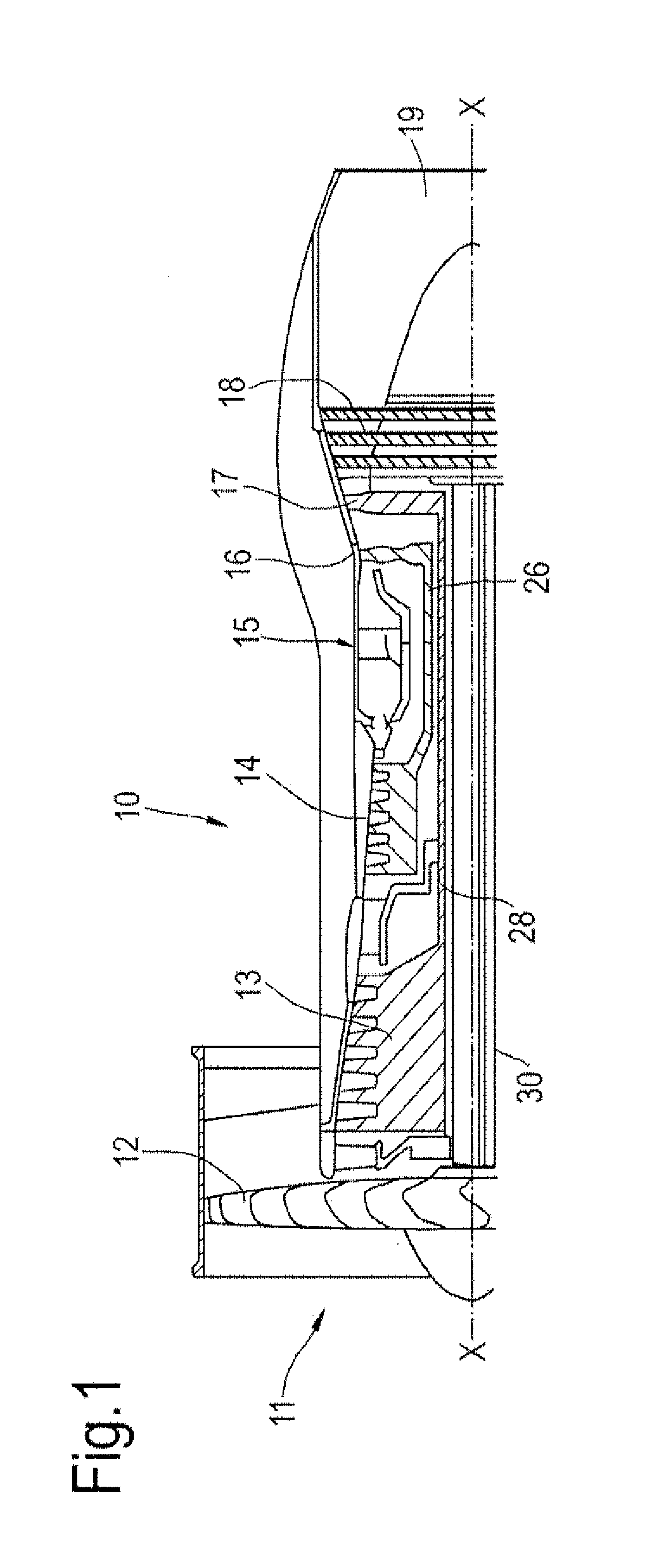
[0044]A turbofan gas turbine engine 10, as shown in FIG. 1, comprises in flow series an intake 11, a fan 12, an intermediate pressure compressor 13, a high pressure compressor 14, a combustion chamber 15, a high pressure turbine 16, an intermediate pressure turbine 17, a low pressure turbine 18 and an exhaust 19. The high pressure turbine 16 is arranged to drive the high pressure compressor 14 via a first shaft 26. The intermediate pressure turbine 17 is arranged to drive the intermediate pressure compressor 13 via a second shaft 28 and the low pressure turbine 18 is arranged to drive the fan 12 via a third shaft 30. In operation air flows into the intake 11 and is compressed by the fan 12. A first portion of the air flows through, and is compressed by, the intermediate pressure compressor 13 and the high pressure compressor 14 and is supplied to the combustion chamber 15. Fuel is injected into the combustion chamber 15 and is burnt in the air to produce hot exhaust gases which flow...


PUM


Abstract

An annular combustion chamber wall arrangement includes an annular wall and a plurality of tiles and each tile is secured to and is spaced from a further annular wall. The first surface of each tile faces the annular wall and the second surface of each tile faces away from the annular wall. Each tile has a plurality of pedestals extending away from the first surface towards the annular wall and / or a plurality of effusion cooling apertures extending through the tile from the first surface to the second surface. At least one of the tiles has the pedestals and / or the effusion cooling apertures arranged in a predetermined pattern which provides the tile with a more uniform stiffness in all directions to reduce the possibility of cracking of the tile. In one predetermined pattern the pedestals are arranged in a Fermat's (parabolic) spiral with the pedestals arranged with Fibonacci number ordering.

Description

FIELD OF THE DISCLOSURE[0001]The present disclosure relates to an annular combustion chamber wall arrangement, in particular relates to a gas turbine engine annular combustion chamber wall arrangement and more particularly relates to a gas turbine engine annular combustion chamber wall and tile arrangement.BACKGROUND TO THE DISCLOSURE[0002]An annular gas turbine engine combustion chamber comprises an annular upstream end wall, an inner annular wall and an outer annular wall. The annular upstream end wall has a plurality of circumferentially spaced apertures and an associated fuel injector is located in each of the apertures in the annular upstream end wall.[0003]Conventionally an annular gas turbine engine combustion chamber is provided with a plurality of heat shields, tiles, arranged downstream of the annular upstream end wall to thermally protect the upstream wall of the combustion chamber. Each heat shield, tile, is provided with a central aperture which is aligned with a corres...

Claims


Application Information

Patent Timeline
Patent Type & Authority Applications(United States)
IPC IPC(8): F23R3/00F23R3/04
CPCF23R3/04F23R3/007F23M5/02F23R3/002F23R3/06F23M2700/0053F23R2900/03041F23R2900/03045
Inventor BALANDIER, QUENTIN LUCCHALMERS, DOUGLAS ALEXANDER
Owner ROLLS ROYCE PLC
Why Eureka
Try Eureka