
Ignition control apparatus for internal combustion engine (as amended)

a control apparatus and internal combustion engine technology, applied in the direction of electric control, anti-theft devices, instruments, etc., can solve the problems of deterioration in the accuracy of determining the flow velocity of in-cylinder gas, and achieve the effect of reliably suppressing a deterioration in combustion and shortening the delay time period

Inactive Publication Date: 2016-01-14
TOYOTA JIDOSHA KK
View PDF3 Cites 6 Cited by
  • Summary
  • Abstract
  • Description
  • Claims
  • Application Information

AI Technical Summary

Benefits of technology

The present invention provides an ignition control apparatus for an internal combustion engine that can suppress a deterioration in the accuracy of determining the flow velocity in-cylinder gas, even in a case where a discharge interruption occurs. By using the discharge energy integration value to determine the flow velocity, the apparatus can prevent a deterioration in combustion and suppress the occurrence of combustion variations in a cycle in which the determined flow velocity of in-cylinder gas is low. Additionally, the apparatus can quickly perform a flow velocity determination based on the size of the discharge voltage, and shorten a delay time period from a flow velocity determination time point until the supply of additional ignition energy is performed. This ensures more reliable suppression of a deterioration in combustion in that cycle.

Problems solved by technology

Therefore, according to the method described in the aforementioned Patent Literature 1, there is a concern that the accuracy of determining the flow velocity of in-cylinder gas will deteriorate if a discharge interruption occurs.

Method used


Image

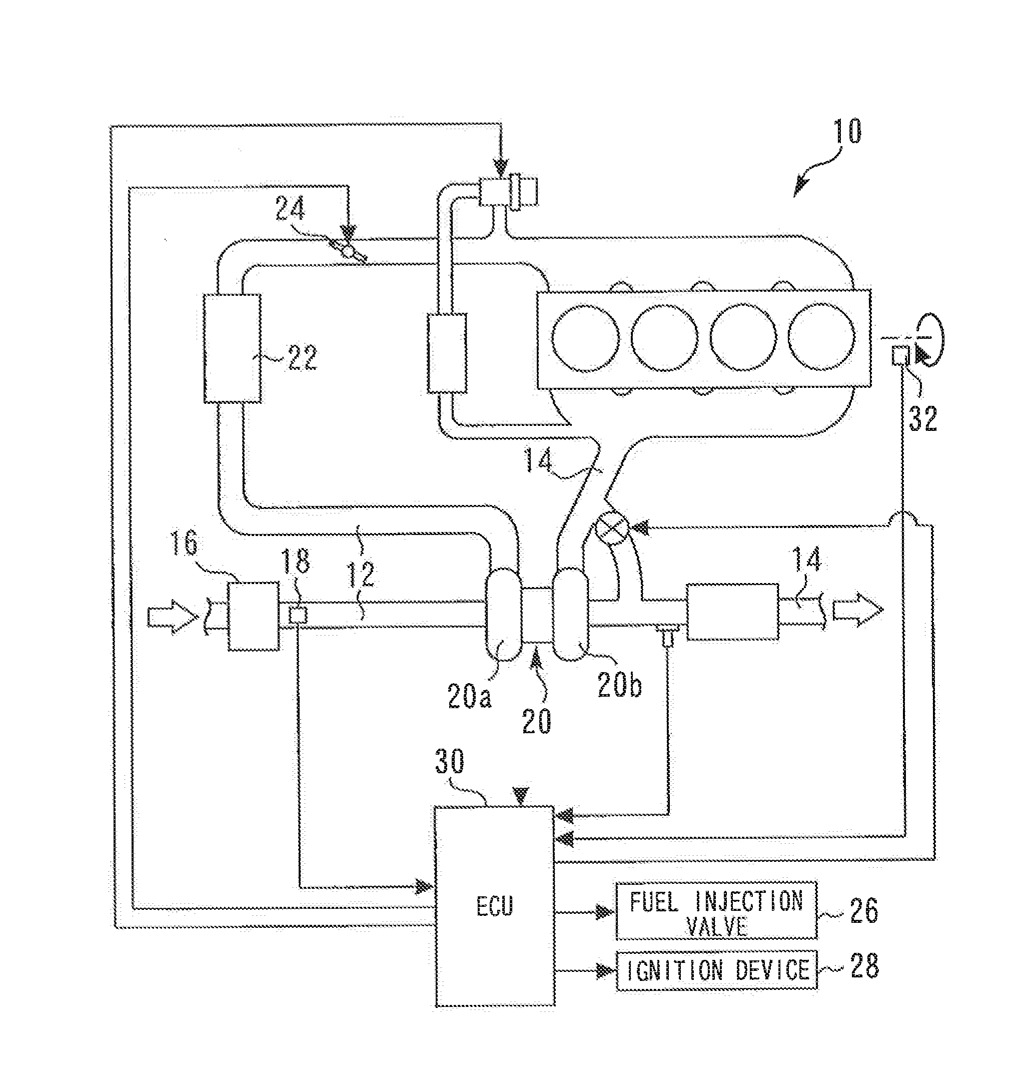
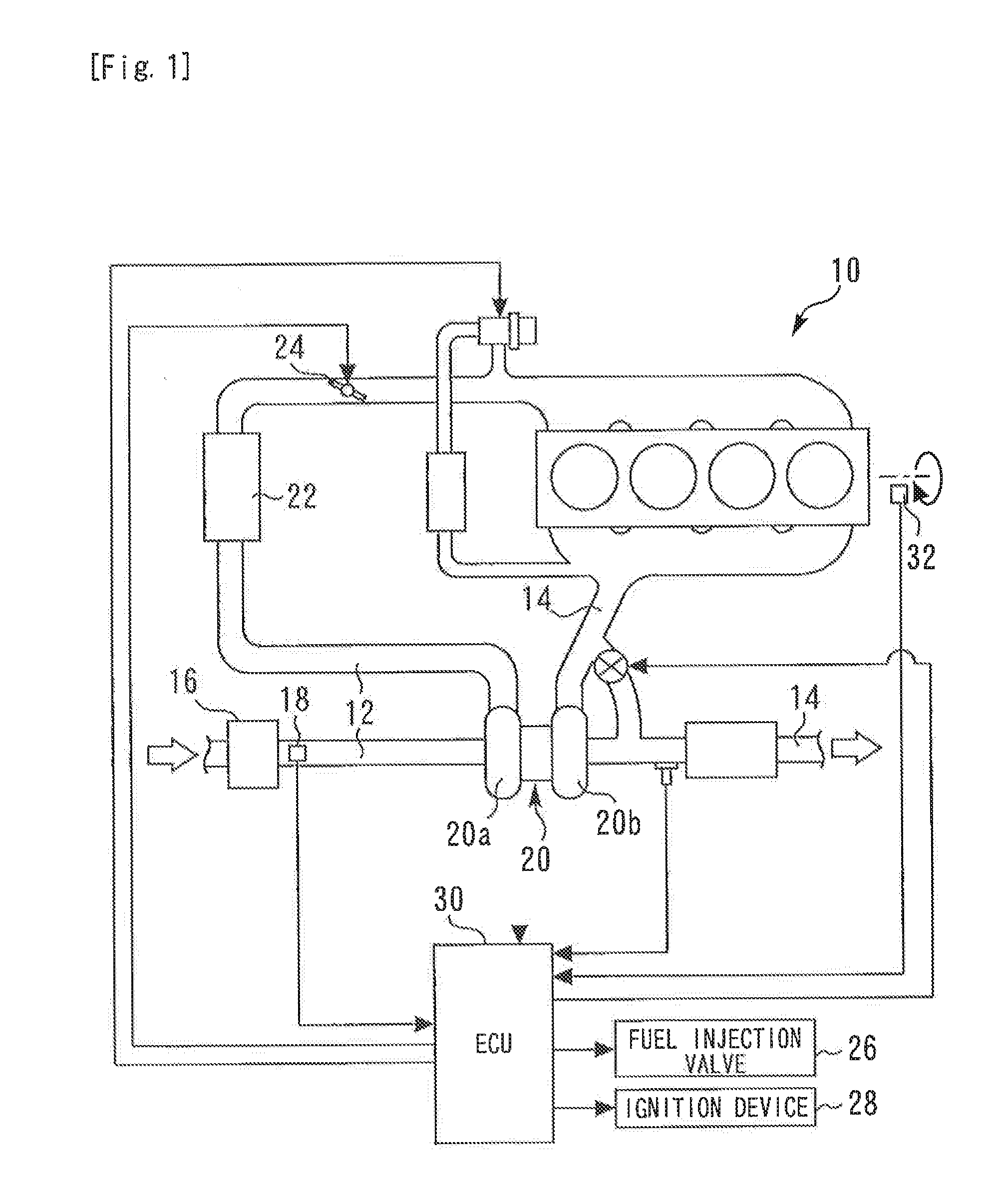
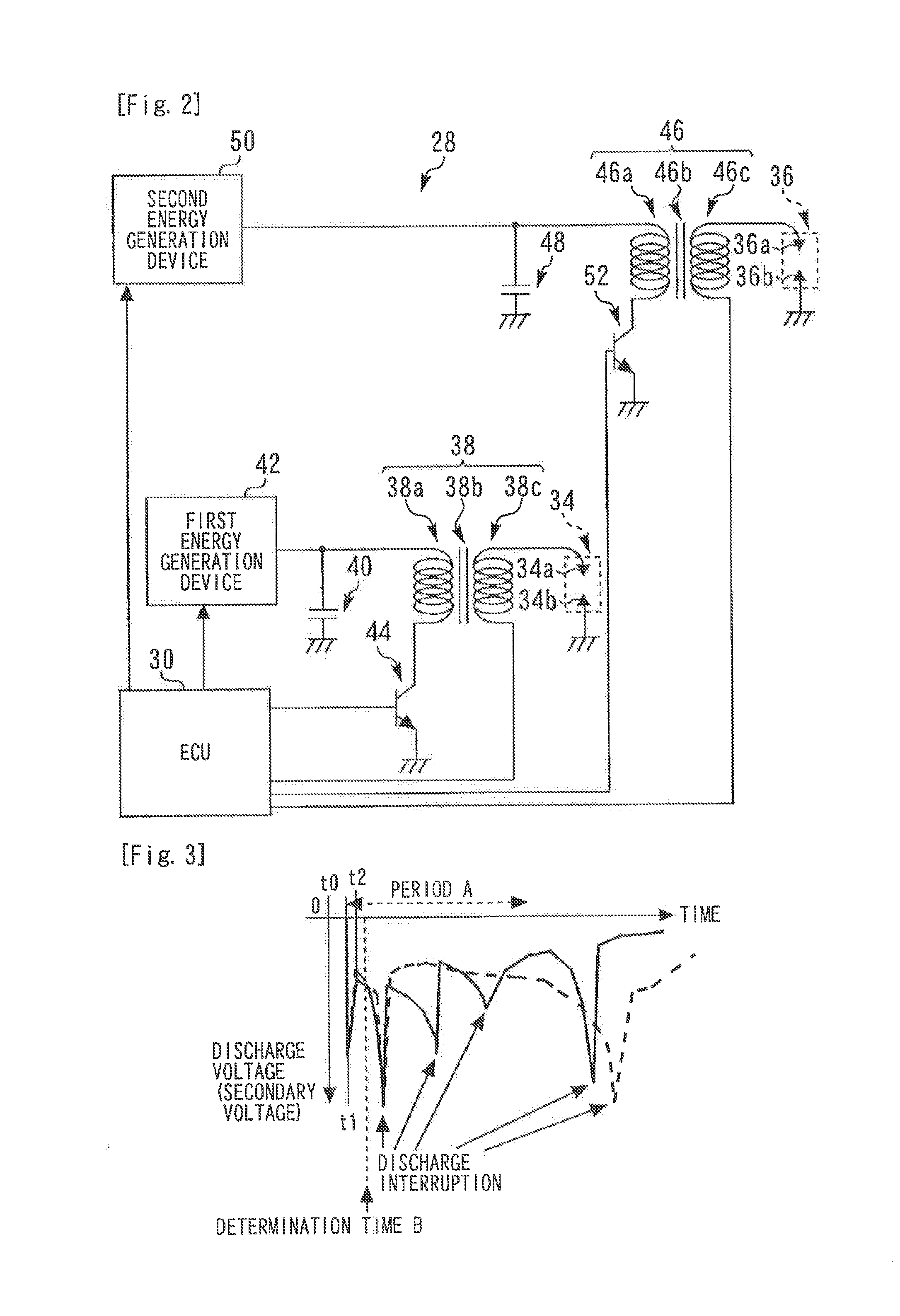
  • Ignition control apparatus for internal combustion engine (as amended)
  • Ignition control apparatus for internal combustion engine (as amended)
  • Ignition control apparatus for internal combustion engine (as amended)

Examples


embodiment 1

Specific Processing in Embodiment 1

[0062]FIG. 6 is a flowchart illustrating a control routine that the ECU 30 executes to realize the characteristic flow velocity determination with respect to the in-cylinder gas and ignition control in Embodiment 1 that is described above. Note that it is assumed that the present routine is started at a timing at which a predetermined spark timing is reached in each cylinder and is repeatedly executed for each predetermined control period.

[0063]According to the routine shown in FIG. 6, first the ECU 30 executes processing to acquire a discharge voltage (secondary voltage) of the first spark plug 34 (step 100), and then executes processing to acquire a discharge current (secondary current) of the first spark plug 34 (step 102).

[0064]Next, using the acquired discharge voltage and discharge current, the ECU 30 calculates a discharge energy integration value by time-integrating the (record of) products of the discharge voltage and the discharge current...

embodiment 2

Specific Processing in Embodiment 2

[0076]FIG. 8 is a flowchart illustrating a routine that the ECU 30 executes in Embodiment 2 to acquire a discharge interruption occurrence timing. Note that it is assumed that the present routine is started at a timing at which a predetermined spark timing is reached in each cylinder, and is repeatedly executed for each predetermined control period.

[0077]According to the routine illustrated in FIG. 8, first the ECU 30 executes processing to acquire a discharge voltage (secondary voltage) of the first spark plug 34 (step 200). Next, the ECU 30 calculates a time differential value of the discharge voltage using a current value and a previous value of the discharge voltage (step 202).

[0078]Thereafter, the ECU 30 determines whether or not the calculated time differential value of the discharge voltage is greater than a predetermined threshold value (step 204), if the result determined is that the time differential value of the discharge voltage is grea...


PUM


Abstract

An ignition control apparatus for an internal combustion engine of the present invention includes a spark plug (34) for igniting an air-fuel mixture in a cylinder, and is configured to be capable of measuring a discharge voltage and a discharge current of the spark plug (34). The ignition control apparatus determines the flow velocity of an in-cylinder gas based on a discharge energy integration value that is obtained by integrating a product of the discharge voltage and the discharge current over a predetermined period.

Description

TECHNICAL FIELD[0001]The present invention relates to an ignition control apparatus for an internal combustion engine.BACKGROUND ART[0002]A control apparatus for a spark-ignition type internal combustion engine has already been disclosed in, for example, Patent Literature 1. The conventional control apparatus is configured to detect a secondary current (discharge current) that flows to a spark plug or a secondary voltage (discharge voltage) that is applied to the spark plug, and to determine whether or not a gas flow velocity in a cylinder is equal to or greater than a determination flow velocity, based on the detected secondary current or secondary voltage.[0003]More specifically, the above described conventional control apparatus determines that the gas flow velocity is equal to or greater than the aforementioned determination flow velocity in a case where a discharge sustaining voltage that is a secondary voltage after a dielectric breakdown voltage has been reached is equal to o...

Claims


Application Information

Patent Timeline
Patent Type & Authority Applications(United States)
IPC IPC(8): F02P9/00F02P17/12F02P17/02
CPCF02P17/12F02P9/002F02P17/02F02D35/021F02D41/18F02P3/05F02P17/00G01F9/001
Inventor KIMURA, KOSHIRO
Owner TOYOTA JIDOSHA KK
Learn More