
Tensionable threaded rebar bolt

a technology of rebar bolts and threaded bolts, which is applied in the direction of threaded fasteners, bolts, screwes, etc., can solve the problems of high cost, slow and costly use of cold-cutting and/or cold-forming processes, and the effect of cost-effectiveness, cost-effectiveness and improved structural capability

Active Publication Date: 2015-12-31
NUCOR CORP
View PDF11 Cites 0 Cited by
  • Summary
  • Abstract
  • Description
  • Claims
  • Application Information

AI Technical Summary

Benefits of technology

This method reduces material and labor costs, improves bolt performance by allowing re-tensioning, and provides a cost-effective solution for producing large quantities of threaded rebar bolts suitable for structural support applications.

Problems solved by technology

Throughout the initial investigation of the invention disclosed in the Fox patents, manufacturing companies have found that there is not a practical method of producing the desired large quantities of bolts for the system because the bolts had to be made from standard merchant round steel bar run through cut-threading or roll-threading machines (e.g., a Landis threading machine), which produce one thread at a time by rotating the head around a stationary round bar and continuing along the shaft a defined length, usually at least 24 inches.
The use of such cold-cutting and / or cold-forming processes is very slow and costly, and as such the manufacturing quantity is restricted and incapable of meeting product demand for the mining bolts at a low cost.
These manufacturing processes can be costly because of the set-up and manufacturing times associated with creating specialized fasteners for various applications.
However, each invention has its own associated problems.
This method is, however complicated by the mandatory employment of two sets of individually synchronized tandem mill rolls rotated at ninety (90) degrees from each other and then synchronized with each other to roll top and bottom threads, and the two side threads, thereby forming a continuous thread for the application of an anchoring or connecting member with a female thread.

Method used


Image

  • Tensionable threaded rebar bolt
  • Tensionable threaded rebar bolt
  • Tensionable threaded rebar bolt

Examples


Embodiment Construction

[0023]Embodiments of the present invention will now be described more fully hereinafter with reference to the accompanying drawings, in which some, but not all, embodiments of the invention are shown. Indeed, the invention may be embodied in many different forms and should not be construed as limited to the embodiments set forth herein; rather, these embodiments are provided so that this disclosure will satisfy applicable legal requirements. Like numbers refer to like elements throughout.

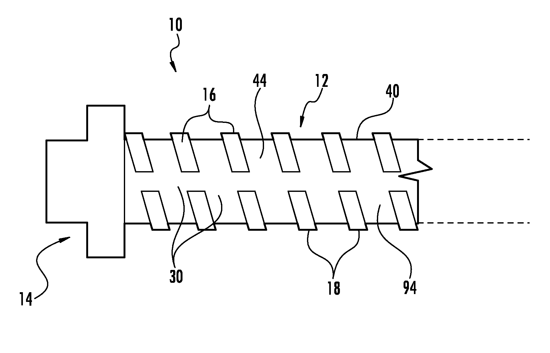
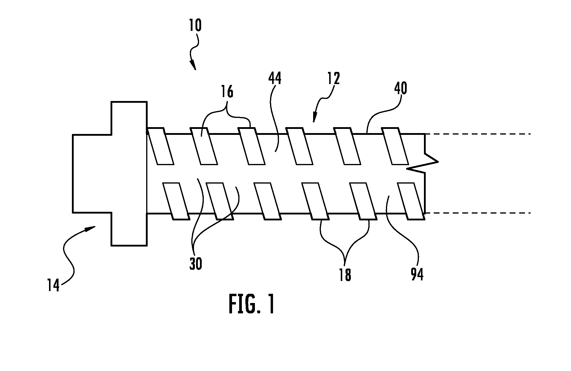
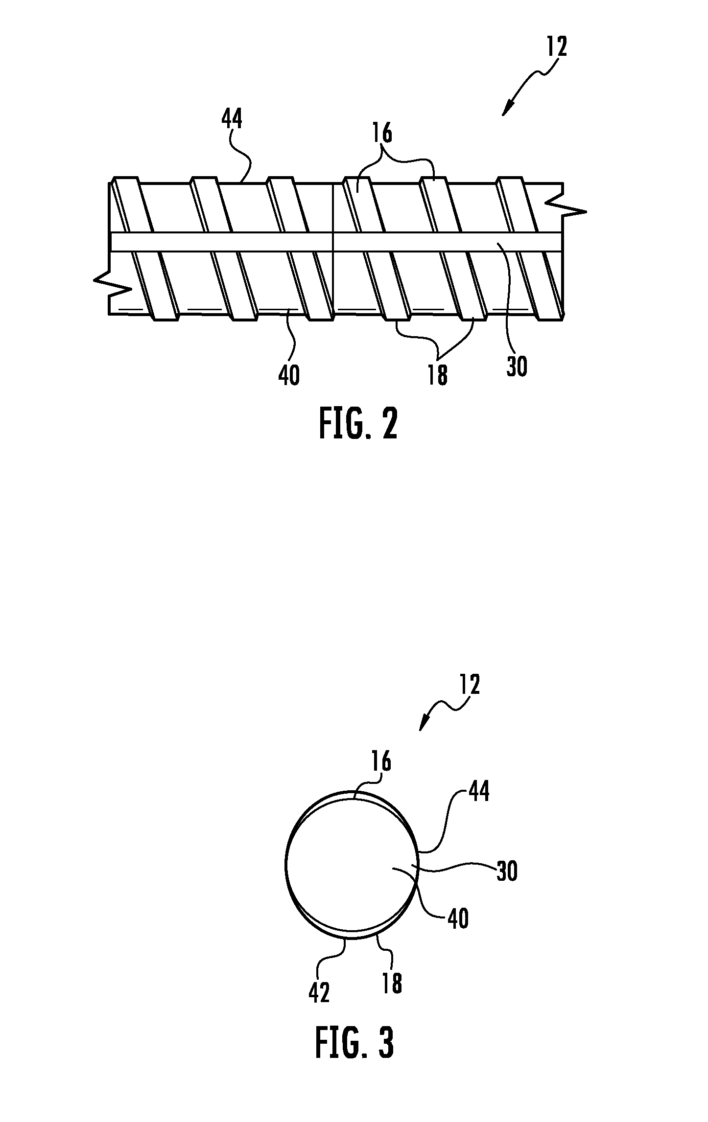
[0024]FIG. 1 illustrates a threaded rebar bolt 10 in accordance with one embodiment of the present invention. As illustrated in FIG. 1, the threaded rebar bolt 10 comprises a shaft 12 and a bolt head 14. The shaft 12 comprises a core 40, a first set of threads 16, and a second set of threads 18. The first set of threads 16 and the second set of threads 18 are aligned to form a semi-continuous thread around the shaft 12 of the threaded bolt 10, such that the threaded bolt can be secured in a correspo...


PUM


Abstract

Embodiments of the present invention include hot-rolled threaded rebar bolts that have a substantially circular core with semi-continuous threads on opposing sides of the rebar bolts. In some embodiments of the invention the shaft is substantially void of longitudinal ribs along at least a portion of the longitudinal area between the first set of threads and the second set of threads of the shaft. The threaded rebar bolt is manufactured in a continuous hot-rolling process to create a threaded rebar shaft with semi-continuous threads and substantially no longitudinal ribs in the longitudinal areas and no additional machining is required to create the threads after the threaded shaft is created from the hot-rolling process.

Description

CLAIM OF PRIORITY UNDER 35 U.S.C. §120[0001]This application is a continuation of, and claims priority to, co-pending U.S. patent application Ser. No. 13 / 805,277, filed on Apr. 25, 2013 and entitled “Tensionable Threaded Rebar Bolt,” which is a national stage application of, and claimed priority to, PCT / US2011 / 041582, filed on Jun. 23, 2011 and entitled “A Tensionable Threaded Rebar Bolt,” which claimed priority to U.S. Provisional Patent Application Ser. No. 61 / 358,355, filed on Jun. 24, 2010 and entitled “System and Method of Making a Spiral Bolt Bar, and Methods of Use”, which are all assigned to the assignee hereof and hereby expressly incorporated by reference herein.FIELD[0002]This invention relates to the field of fasteners, and more particularly to hot-rolled threaded rebar bolts for use in various applications, such as but not limited to mine roof bolting technology for use with resin nuts, concrete support structure applications, or other similar support structure mediums....

Claims


Application Information

Patent Timeline
Patent Type & Authority Applications(United States)
IPC IPC(8): E04C5/02
CPCE21D21/004E04C5/02E21D21/008E21D20/025
Inventor WOOD, CHARLES D.
Owner NUCOR CORP
Learn More