
Authentication Device & Related Methods

Inactive Publication Date: 2015-12-24
LICENTIA GROUP +1
View PDF3 Cites 19 Cited by
  • Summary
  • Abstract
  • Description
  • Claims
  • Application Information

AI Technical Summary

Benefits of technology

This patent describes a device that provides secure and verifiable user input through a pinpad without storing session keys vulnerable to theft or unauthorized access. The device uses an image of a scrambled pinpad received from a remote server and generates an operable pinpad in memory. The user's keystroke is recorded when they touch the screen, and the image is deleted from the device's memory afterward, ensuring secure input. The device is cost-effective and easy to use compared to conventional card payment terminals. Additionally, the device may have a camera for capturing the user's image, providing further security.

Problems solved by technology

If the entered and stored PINs do not match then the operation fails.
If the operation was unsuccessful this would normally be due to insufficient funds.
However, if the message from the issuing bank indicates that the card is identified as being stolen, a prompt on the terminal may instruct the retailer to keep the card.
However, known problems exist in respect of the current systems.
This, in turn, imposes a cost implication for terminal manufacturers.
Terminals can therefore be costly, sometimes up to several thousand pounds per device.
However, in some countries e.g. the UK, online verification is not available.
Therefore, retailers have no real commercial option but to pay for the costly PCI compliant terminals if they want to be able to accept their customers' payment cards.
In addition, if the terminal were to be compromised, and there have been several known incidents where this is the case, the user's PIN would be accessible to unauthorised parties.
Again, this adds to the complexity and cost of the terminal.
Therefore, the device may not comprise mechanical, depressible keys.
Preferably, the device is not configured for compliance with EMV or PCI standards.
Additionally or alternatively, the device is not configured for secure storage of a bank session key.

Method used


Image

  • Authentication Device & Related Methods
  • Authentication Device & Related Methods
  • Authentication Device & Related Methods

Examples


Embodiment Construction

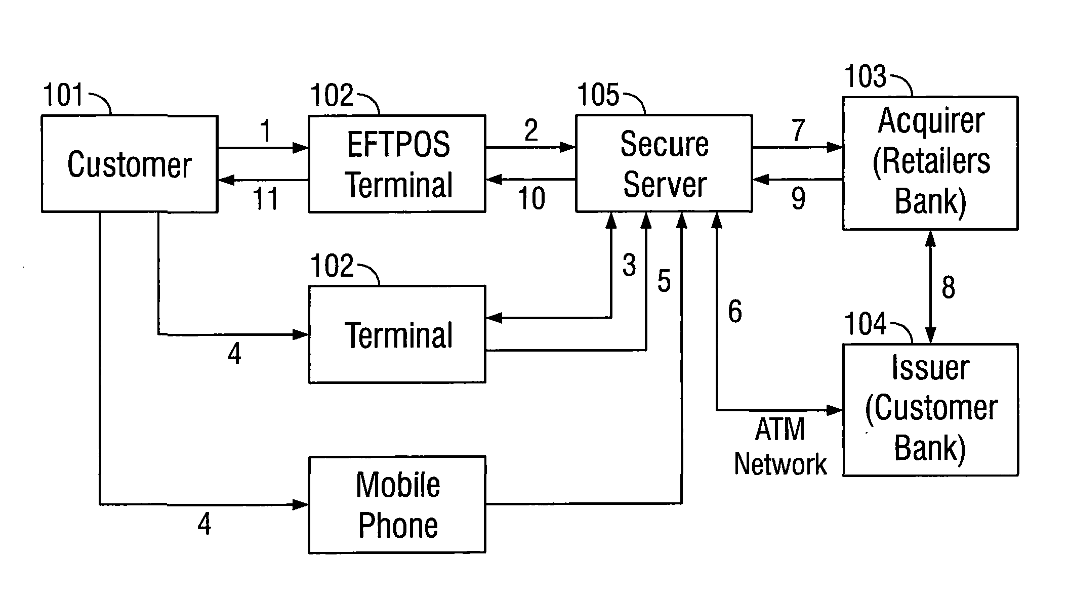
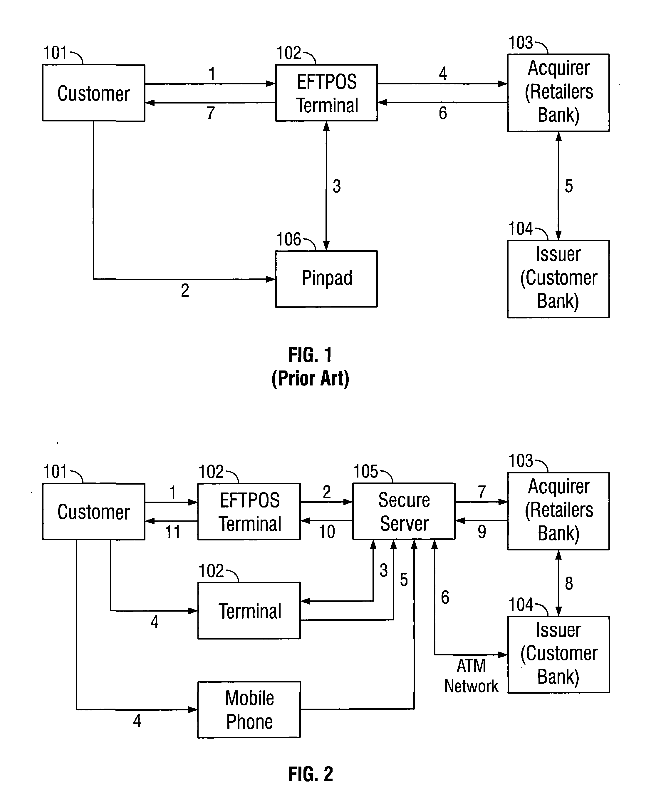
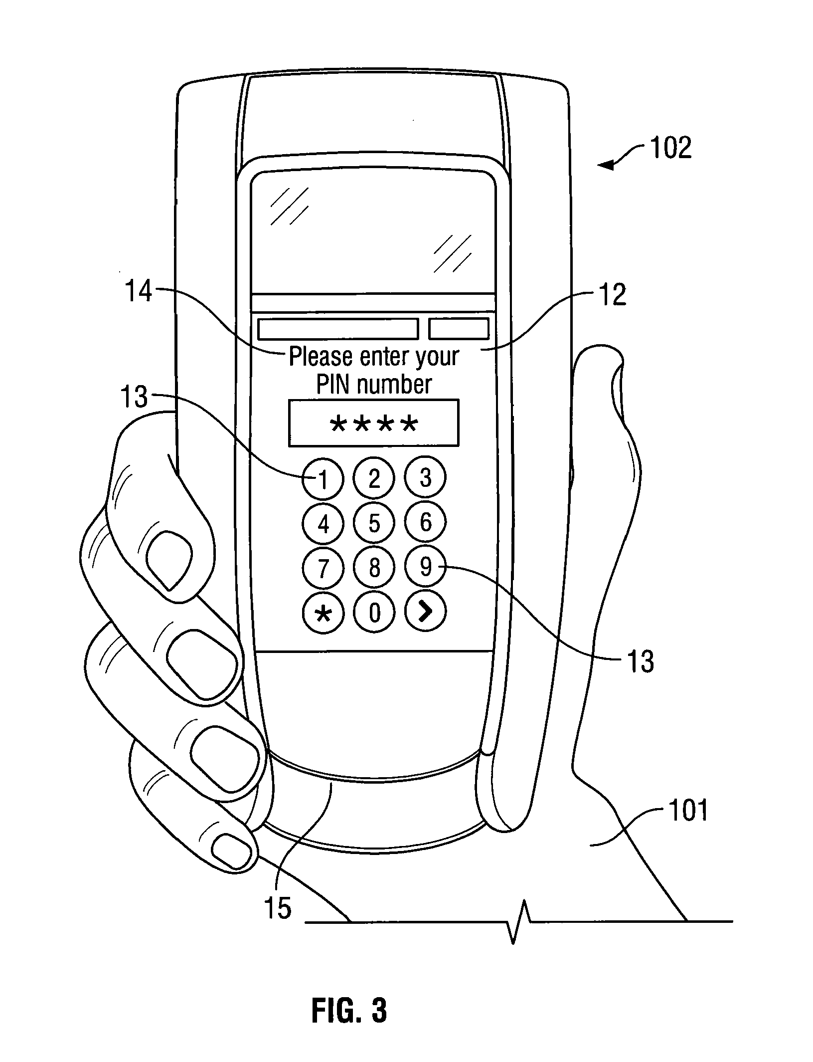
[0118]FIG. 3 shows an illustrative embodiment of the present invention. The invention provides a PIN capture device 102. It is configured such that it can be held in one or both hands by the user 101 as shown. The terminal 102 looks like a conventional PCI compliant terminal in all respects except that internally it does not have the ability to securely store a bank session key. The terminal has a touch screen 12 which is able to display a virtual keypad comprising a plurality of keys 13. The screen is also able to display messages and prompts 14 as well as read input from the user 101 when the user presses a key 13. The terminal has a card reading arrangement 15. In FIG. 3, this is shown as a slot or recess into which a payment card with a chip may be inserted. A contactless card reader may be used in addition to or as an alternative to the slot, as may a magnetic strip reader.

[0119]In an embodiment of the invention, when a customer wishes to make a transaction at a retailer's prem...


PUM


Abstract

The invention provides a portable device for input of a Personal Identification Code (PIC). It comprises a card reading component and a touch screen. The screen is arranged and configured to display a pinpad and receive a PIC upon entry by a user via the pinpad. The card reading component and the touch screen are integral to the input device. The device can comprise a mobile phone, which may have a camera. The device can be a handheld card payment terminal for use in fmancial transactions, where a user's PIN must be authenticated. A security mechanism may be used with the device wherein an image of a scrambled keypad is displayed over an operable keypad, this enabling the device to store an encoded version of the user's input. As the user's real PIN is never stored in the device, no bank session key needs to be stored or encrypted. This enables the terminal to be produced at a lower cost than prior art arrangements.

Description

CROSS-REFERENCE TO RELATED APPLICATIONS[0001]This application is the national stage of International Patent Application No. PCT / GB2014 / 050034 filed on Jan. 7, 2014, and which claims priority to British Patent Applications No. GB 1300923.8 filed on Jan. 18, 2013, and GB 1321505.8 filed on Dec. 5, 2013, all of which are hereby incorporated by reference in their entireties as if fully set forth herein.BACKGROUND[0002]1. Field[0003]This invention relates generally to verification techniques and devices; and, more particularly, to devices and methods for the verification of an individual's identity, possibly via the use of a Personal Identification Code (PIC). The invention is suited for use in situations where verification must be performed before access is granted to some type of controlled resource. It is particularly suited for use with mobile and / or handheld devices which are provided with telecommunications functionality, such as mobile phones, portable computing devices etc. It ma...

Claims


Application Information

Patent Timeline
IPC IPC(8): G06Q20/32G06Q20/40
CPCG06Q20/4012G06Q20/3226G06Q20/322G07F7/0886G07F7/1033G07F7/122G07F7/0873
Inventor PIKE, JUSTIN
Owner LICENTIA GROUP
Learn More