
Check valve for ventilation or outlet openings of compressed air apparatuses in vehicles

a technology of check valves and compressed air apparatuses, which is applied in the direction of engine diaphragms, braking systems, functional valve types, etc., can solve problems such as difficult latency, and achieve satisfactory sealing properties and low noise developmen

Active Publication Date: 2015-12-24
KNORR-BREMSE SYST FUER NUTZFAHRZEUGE GMBH
View PDF1 Cites 0 Cited by
  • Summary
  • Abstract
  • Description
  • Claims
  • Application Information

AI Technical Summary

Benefits of technology

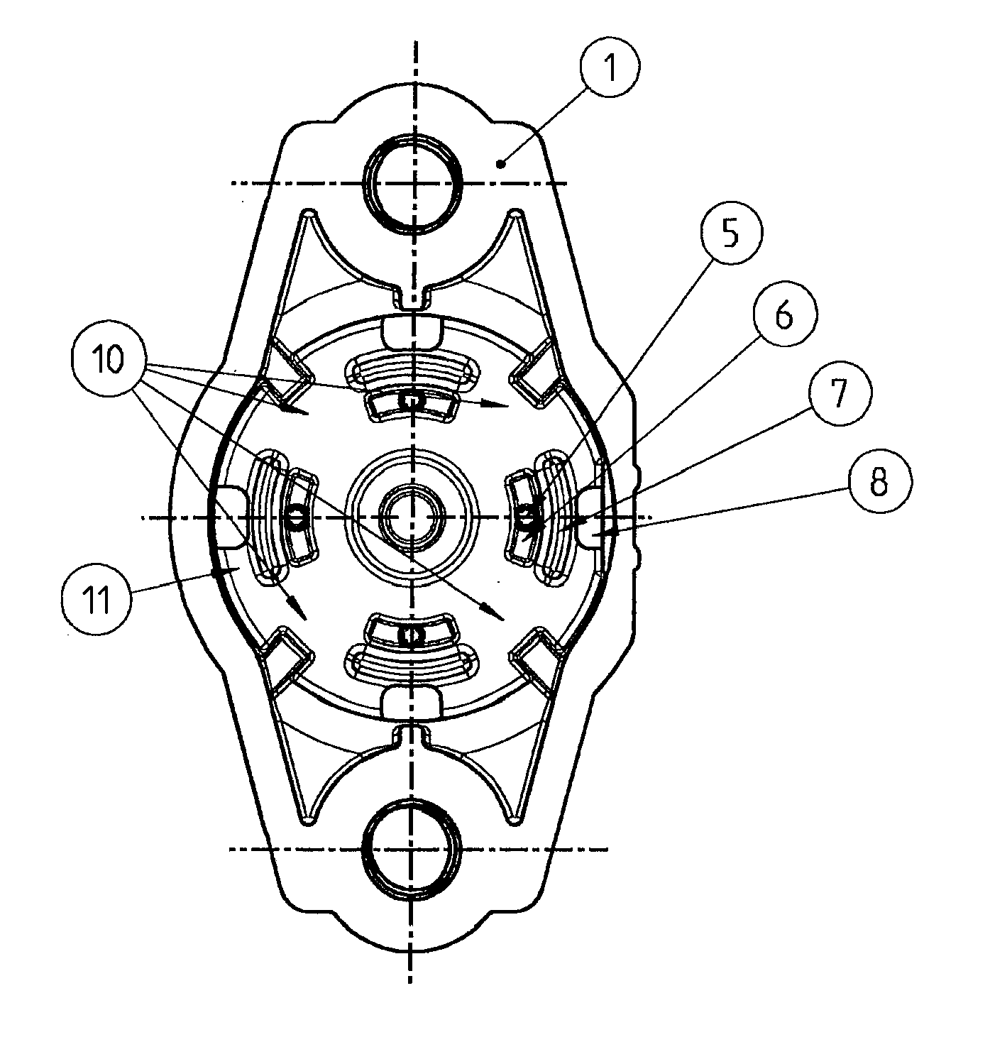
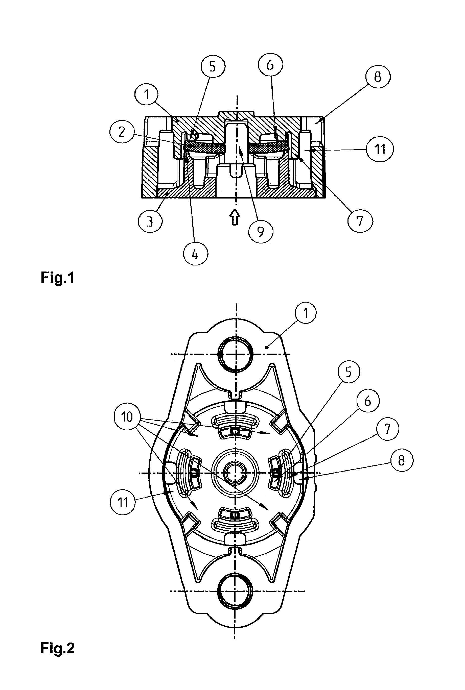
The invention aims to create a ventilation or check valve that reduces noise and improves seal properties. This is achieved by designing the diaphragm disk so that it only lifts up from the valve seat in small sections, reducing the amount of air that can create noise. The valve also includes hold-downs that improve the rigidity of the diaphragm on the valve housing, preventing the diaphragm from oscillating over a large area and producing less air-borne sound. The valve also has high air throughput, low throttling effects, reliable blocking of undesired flow directions, prevents dirt penetration, and low opening pressure. The cover of the valve housing with the hold-downs helps in protecting the diaphragm and preventing damage and dirt penetration. The valve also has wall sections of arcuate cross-section between the ventilation openings and the hold-downs to shield the diaphragm and valve seat from environmental and flow influences.

Problems solved by technology

The latter has proven difficult, however, since high noise development is to be observed, above all, in the case of relatively compliant material of the diaphragm because the compliant diaphragm can then be excited more readily by the air flow to perform oscillations (solid-borne sound) which cause corresponding air-borne sound.

Method used


Image

  • Check valve for ventilation or outlet openings of compressed air apparatuses in vehicles
  • Check valve for ventilation or outlet openings of compressed air apparatuses in vehicles

Examples


Embodiment Construction

[0032]The ventilation or check valve which is shown in cross section in FIG. 1 is integrated, for example, into an outlet ventilation opening of a compressed air duct of an ABS pressure control valve (ABS valve) or a traction control valve (ASR valve) (not shown here for reasons of scale) of a pneumatic or electropneumatic brake system of a commercial vehicle. The ventilation or check valve then serves to make a flow possible (symbolized by the arrow in FIG. 1) from the compressed air duct, which opens via the outlet or ventilation opening to atmosphere, to atmosphere, but to prevent a flow in the opposite direction.

[0033]The ventilation or check valve is a diaphragm valve and opens as soon as a pressure difference between the compressed air duct and atmosphere has reached or exceeded the opening pressure of the ventilation or check valve. This is the case in the application described here, for example, if the electromagnetic outlet valve of the ABS valve or the ASR valve is opened ...


PUM


Abstract

A ventilation or check valve for ventilation or outlet openings of compressed air apparatuses of vehicles, includes at least one diaphragm disk which is made from flexible material, is held with a central region in a bore of a valve housing and is prestressed with a radially outer region against a valve seat on the valve housing, to lift up from the valve seat in a pressure-induced manner in the case of a pressure gradient between an inlet space and an outlet space or atmosphere and to open a flow cross section between the inlet space and the outlet space or atmosphere, in which, as viewed in the circumferential direction of the diaphragm disk, a plurality of hold-downs which are arranged at a circumferential spacing from one another and hold down the radially outer region of the diaphragm disk locally against the valve seat are provided on the valve housing.

Description

FIELD OF THE INVENTION[0001]The present invention relates to a ventilation or check valve for ventilation or outlet openings of compressed air apparatuses of vehicles, comprising at least one diaphragm disk which is made from flexible material, is held with a central region in a bore of a valve housing and is prestressed with a radially outer region against a valve seat on the valve housing, in order to lift up from the valve seat in a pressure-induced manner in the case of a pressure gradient between an inlet space and an outlet space or atmosphere and to open a flow cross section between the inlet space and the outlet space or atmosphere.BACKGROUND INFORMATION[0002]A ventilation or check valve of this type is discussed in DE 19 38 206 A which forms the generic type, and is, for example, a constituent part of an electropneumatic ABS pressure control valve according to DE 197 01 200 C2 from the applicant of the present patent application. According to the embodiment which is shown t...

Claims


Application Information

Patent Timeline
IPC IPC(8): F16K15/14B60T17/04B60T13/26F16K24/04F16K31/126
CPCF16K15/144F16K24/04Y10T137/7904B60T13/26B60T17/04F16K31/126F16K7/12
Inventor GREBE, JANBEMETZ, THOMASMENYHART, LASZLOFOJTYIK, GABOR
Owner KNORR-BREMSE SYST FUER NUTZFAHRZEUGE GMBH
Learn More