
Method for holding brazing material during a brazing operation

a technology of sintering and brazing material, which is applied in the direction of turbines, soldering devices, auxilary welding devices, etc., can solve the problems of compromising the operation of gas turbines, affecting the quality of sintering materials, etc., and achieves low cost and low heat input precision.

Inactive Publication Date: 2015-12-17
SIEMENS ENERGY INC
View PDF11 Cites 11 Cited by
  • Summary
  • Abstract
  • Description
  • Claims
  • Application Information

AI Technical Summary

Benefits of technology

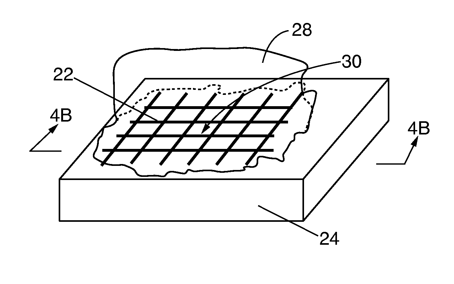
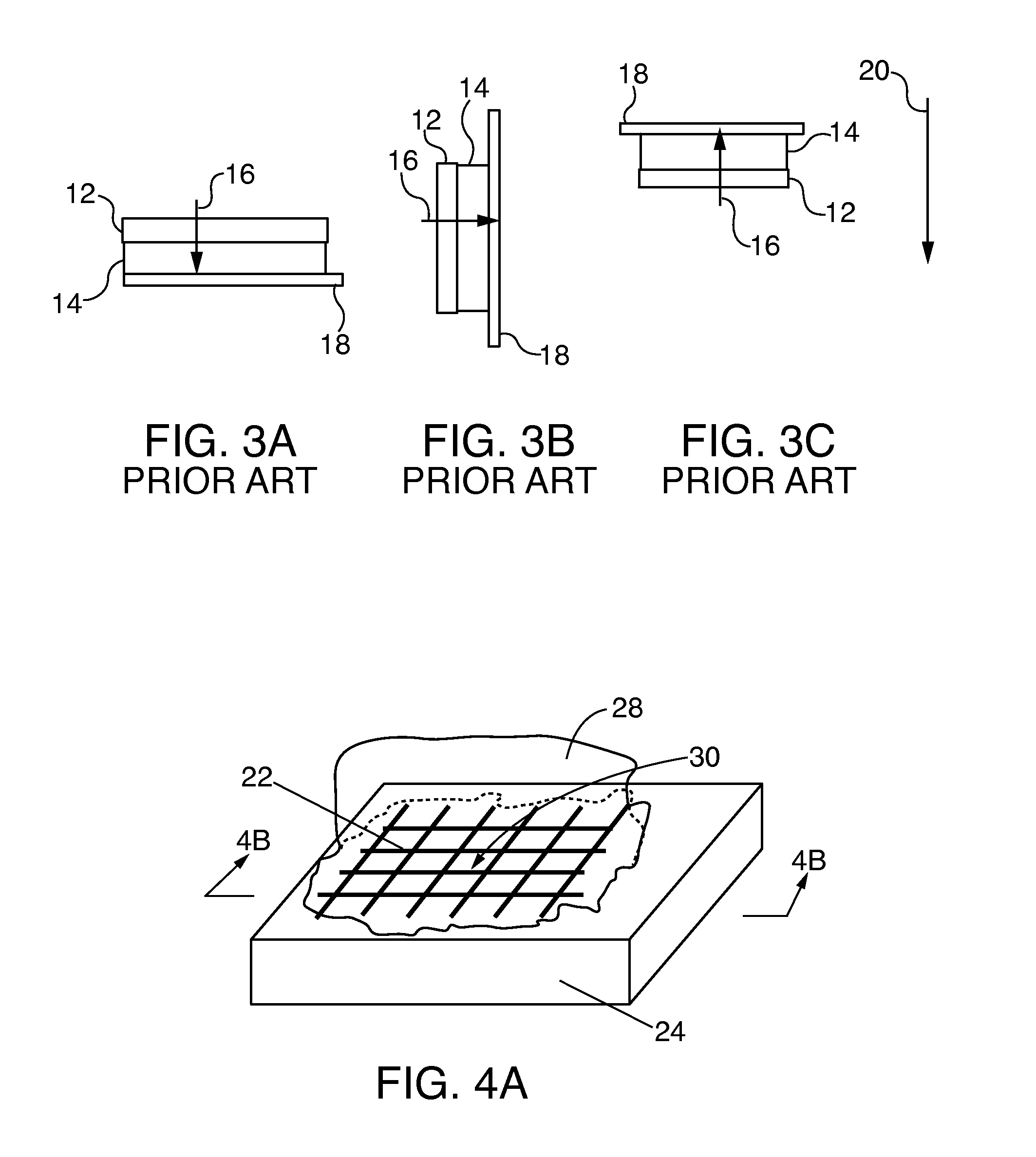
[0013]A method is disclosed for holding a sintering filler material during a brazing / sintering operation for repairing a damaged area of a component wherein the component is in either bonding face vertical position or bonding face up position. The method includes providing a wire mesh and attaching the wire mesh to the component in a location corresponding to the damaged area by any low cost and low heat input precision fusion welding method such as micro resistance spot welding. In one embodiment, the sintering filler material is pushed through the mesh thereby inserting the sintering filler material between the wire mesh and the damaged area thus securing the sintering filler material. Alternatively, a first quantity of sintering filler material is applied to the damaged area before the wire mesh is attached. The wire mesh is then attached to the component such that the wire mesh is on top of and contacts the first quantity while also surrounding the first quantity thus forming a gap. A second quantity of sintering filler material is then applied onto the wire mesh such that the wire mesh is at an interface between the first and second quantities of sintering filler material. In another technique, a full quantity of sintering filler material equivalent to the first and second quantities is applied to the damaged area before the wire mesh is attached. The wire mesh is then positioned over the full quantity of sintering filler material and attached to the component such that the wire mesh surrounds the amount to form a gap.

Problems solved by technology

The existence of such damage compromises operation of the gas turbine and may jeopardize safety.
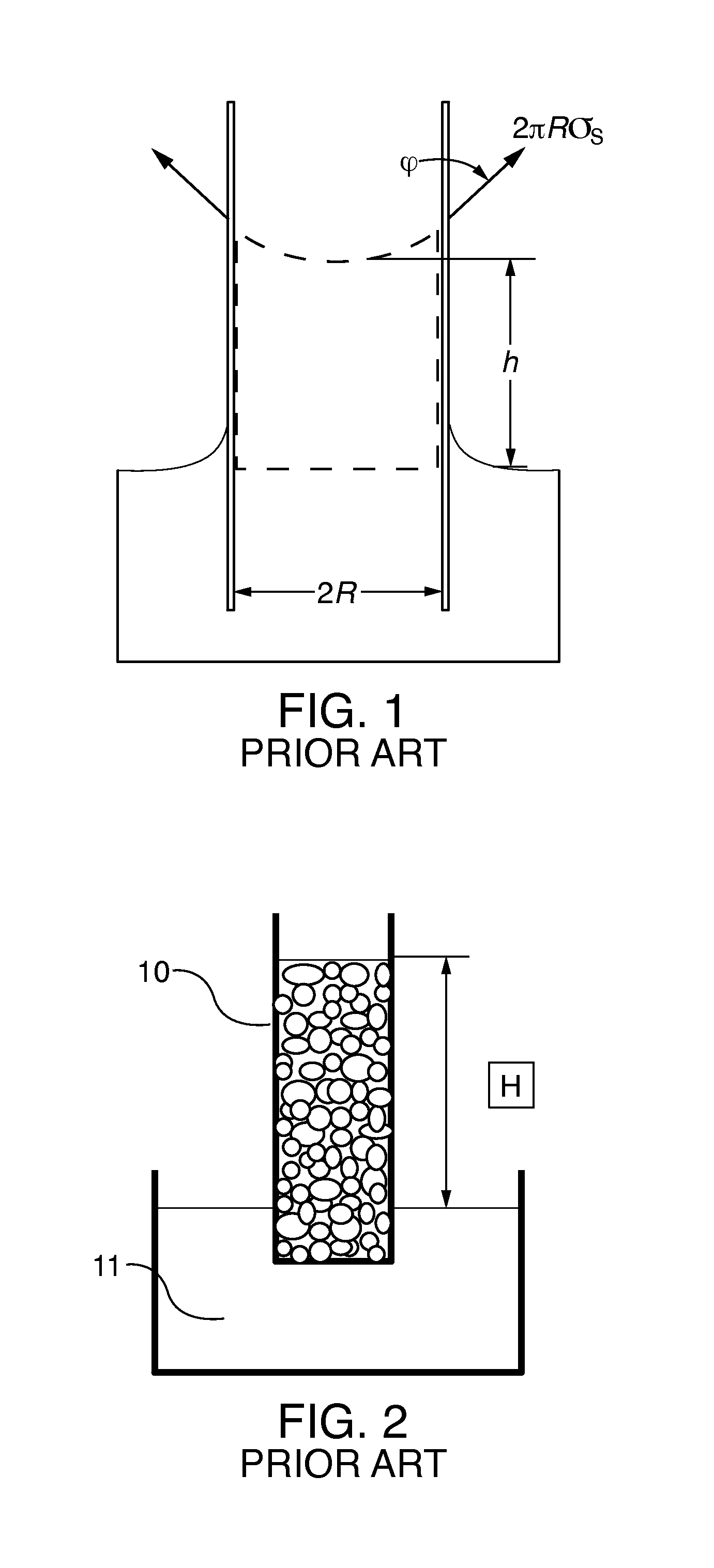
Therefore, capillary force varies and is a challenging process variable for braze repair operations.
This adds to the undesirable effects due to gravity on a repair with respect to positions other than the bonding face down position.
A first undesirable effect is possible repair filler detachment (or partial detachment) at repair sites which could lead to repair failure.
This occurs since gravity works against filler / repair site adhesion and also since organic adhesives / binders will be burned out at temperatures far lower than braze melting temperatures.
A second undesirable effect is repair filler creep, due to gravity, during a transient semi-liquid stage of the repair process which leads to poor repair dimension control.
A third undesirable effect is that gravity influences the sponge infiltration process which could lead to a poor sintered deposit / base alloy bonding interface.
A fourth undesirable effect is that gravity influences a repair filler consolidation process during and immediately after liquid braze infiltration, resulting in increased porosities in sintered filler deposits.
The first and second undesirable effects are the most pressing since the repairs may fail on a macroscopic scale.
The possibility of macroscopic repair failures are particularly high if the sintering filler material deposits are very heavy when dealing with severe erosion damage repairs.
The third and fourth undesirable effects occur on a microscopic level and are critical for sintering repair qualification.
However, if multiple damaged areas exist on the component, multiple furnace brazing cycles are typically required which significantly increases processing time and repair cost.
Further, multiple brazing cycles increase the possibility of repair site re-contamination resulting in reduced repair quality.
Therefore, additional cleaning operations may be required, thus further increasing costs.

Method used


Image

  • Method for holding brazing material during a brazing operation
  • Method for holding brazing material during a brazing operation
  • Method for holding brazing material during a brazing operation

Examples


Embodiment Construction

[0030]Although various embodiments that incorporate the teachings of the present invention have been shown and described in detail herein, those skilled in the art can readily devise many other varied embodiments that still incorporate these teachings. The invention is not limited in its application to the exemplary embodiment details of construction and the arrangement of components set forth in the description or illustrated in the drawings. The invention is capable of other embodiments and of being practiced or of being carried out in various ways. Also, it is to be understood that the phraseology and terminology used herein is for the purpose of description and should not be regarded as limiting. The use of “including,”“comprising,” or “having” and variations thereof herein is meant to encompass the items listed thereafter and equivalents thereof as web as additional items. Unless specified or limited otherwise, the terms “mounted,”“connected,”“supported,” and “coupled” and vari...


PUM

PropertyMeasurementUnit
thickaaaaaaaaaa
diameteraaaaaaaaaa
distancesaaaaaaaaaa

Abstract

A method for holding a sintering filler material during a brazing / sintering operation for repairing a damaged area of a component wherein the component is in either a bonding face down position, bonding face vertical position or bonding face up position. The method includes providing a wire mesh and attaching the wire mesh to the component in a location corresponding to the damaged area. Further, the method includes forming a gap between the wire mesh and the component. Moreover, the sintering filler material may be inside the wire mesh or both inside and outside the wire mesh in order to secure the sintering filler material to the damaged area.

Description

CROSS REFERENCE TO RELATED APPLICATIONS[0001]The entire disclosure of U.S. patent application Ser. No. 14 / 134,212, filed on Dec. 19, 2013, Attorney Docket No. 2013P20861US, and entitled PLURAL LAYER PUTTY-POWDER / SLURRY APPLICATION METHOD FOR SUPERALLOY COMPONENT CRACK VACUUM FURNACE HEALING is hereby incorporated by reference in its entirety.FIELD OF THE INVENTION[0002]The invention relates to methods for performing a high temperature vacuum brazing / sintering operation, and more particularly, to a method for holding a sintering filler material with a wire mesh to enable repairing of a damaged area of a component when the component is in different orientations against gravity, either a bonding face down position, bonding face vertical position or bonding face up position to minimize possible negative impacts of gravity on this operation.BACKGROUND OF THE INVENTION[0003]A typical gas turbine engine includes a compressor section, a combustion section and a turbine section. The compress...

Claims


Application Information

Patent Timeline
Patent Type & Authority Applications(United States)
IPC IPC(8): B23K37/06B23K1/00B23P6/00B23K1/20
CPCB23K37/06B23P6/007B23K1/00B23K1/206B23P6/045B23K1/0018B23K3/087B23K2101/001B23P6/04F01D5/005F01D9/02F05D2220/32F05D2230/22F05D2230/80F05D2300/175
Inventor LI, HANGGARCIA, MARK A.GHUNAKIKAR, SOMESH J.LOWE, WILLIAM J.
Owner SIEMENS ENERGY INC
Learn More