
Handheld power tool and impact block return device thereof

a technology of impact block and return device, which is applied in the direction of manufacturing tools, stapling tools, nailing tools, etc., can solve the problems of affecting the operation of nail shooting, the inability of the firing pin to be moved right back to the start position, and the inability of the nail gun to achieve the expected power and effect, etc., to achieve the effect of improving the stability of impact block retracting and increasing stability

Active Publication Date: 2015-12-10
BASSO IND CORP
View PDF26 Cites 38 Cited by
  • Summary
  • Abstract
  • Description
  • Claims
  • Application Information

AI Technical Summary

Benefits of technology

This patent is for a handheld power tool with a device to prevent the impact block (firing pin) from hitting the tool when it is in use. The device uses a clamping member to keep the impact block in place, making it less likely to move during use. This prevents the impact block from hitting the tool, reducing the chance of damage. The power tool also has a special assembly that ensures the impact block only moves in one direction, further improving its stability during use. Overall, this invention makes the tool safer and more stable during use.

Problems solved by technology

However, in the process of retracting the firing pin as known in conventional nail guns, the firing pin often cannot be moved right back to the start position due to inappropriate internal structural design or suffering from external forces.
Such nail guns often cannot achieve expected power and effect on the next shooting and thus the operation of nail shooting is affected.
As for mechanical element design, the driver member has uneven overall thickness duo to the protrusions fabricated at the two sides thereof, and thus is weak in strength, easy to be damaged, and high in manufacturing cost.
As for operational performance, the driver member may suffer from a great deal of deformation during the heating process and this may probably result in size mismatches between various components, thereby leading the operations to be more unstable.

Method used


Image

  • Handheld power tool and impact block return device thereof
  • Handheld power tool and impact block return device thereof
  • Handheld power tool and impact block return device thereof

Examples


Embodiment Construction

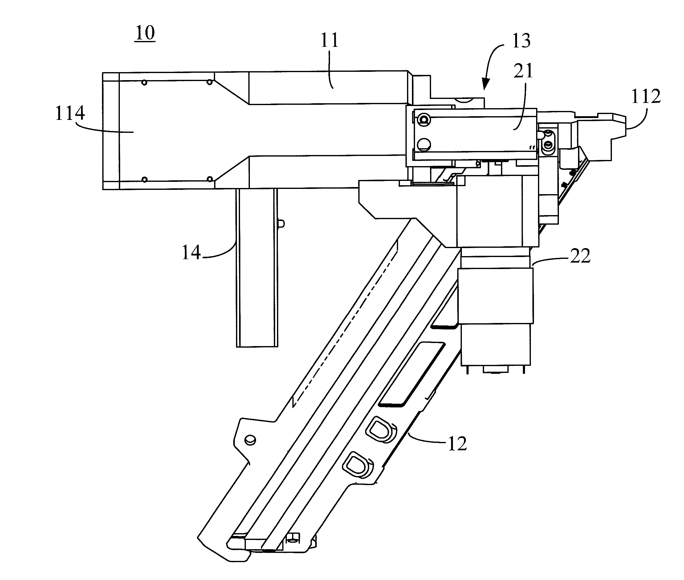
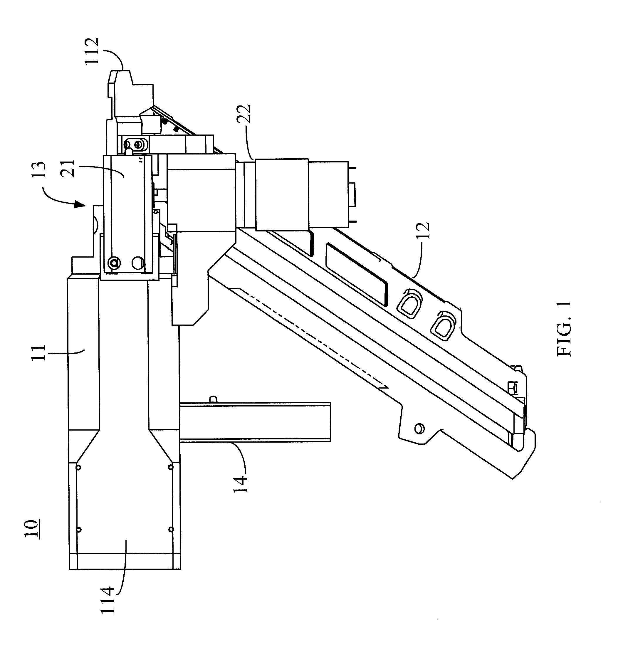
[0021]FIG. 1 is a schematic diagram showing a handheld power tool 10 in accordance with the present invention. For the handheld power tool 10 (e.g., a power actuated nail gun) shown in FIG. 1, only the parts carrying out the technical effects of the present invention are shown, instead of all parts of a manufactured product. It should be understood that the handheld power tool 10 shown in FIG. 1 is merely for illustrating the present invention.

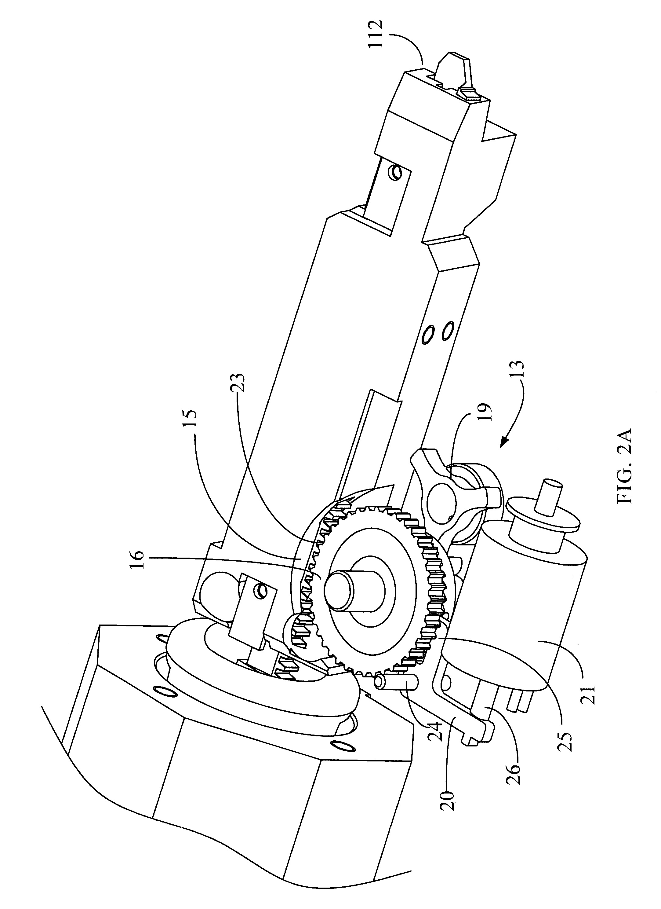
[0022]As shown in FIG. 1, the handheld power tool 10 comprises a main body 11, a nail magazine 12, an impact block return device 13, and a start switch 14. The main body 11 has an exit 112 at one end thereof, which communicates with the nail magazine 12 and the impact block return device 13. The main body 11 has a compressed air chamber 114 at the other end thereof, which accommodates an impact block 15 (see FIG. 2A). The impact block return device 13 is disposed between the compressed air chamber 114 and the exit 112. Nails (or called fastene...


PUM


Abstract

The present invention provides a handheld power tool having an impact block and an impact block return device. The impact block has a plurality of continuous teeth arranged along a lengthwise direction of the impact block. The impact block return device comprises a gearwheel engaged with the teeth of the impact block; a ratchet wheel rotating simultaneously with the gearwheel; and a clamping member operated in a first state and a second state, the clamping member contacting the ratchet wheel in the first state and the clamping member being separated from the ratchet wheel in the second state; wherein the impact block only can do a single-directional movement when the clamping member contacts the ratchet wheel in the first state. The present invention can improve stability of the retraction process of the impact block (e.g., a firing pin).

Description

TECHNICAL FIELD OF THE INVENTION[0001]The present invention relates to a handheld power tool, and more particularly, to an impact block return device of the handheld power tool.BACKGROUND OF THE INVENTION[0002]During a shooting or launching stage of a nail gun among conventional power tools, a firing pin passes dynamic energy to a nail such that the nail is stuck into a workpiece from the surface of the workpiece. After completed in shooting, the firing pin has to be moved back to a start position and waits for a next shooting. However, in the process of retracting the firing pin as known in conventional nail guns, the firing pin often cannot be moved right back to the start position due to inappropriate internal structural design or suffering from external forces. Such nail guns often cannot achieve expected power and effect on the next shooting and thus the operation of nail shooting is affected.[0003]It has been disclosed a conventional nail driving tool in Taiwan Patent Publicat...

Claims


Application Information

Patent Timeline
Patent Type & Authority Applications(United States)
IPC IPC(8): B25C1/04B25C1/06
CPCB25C1/06B25C1/047
Inventor CHIEN, CHIA-YU
Owner BASSO IND CORP
Learn More