
Multi-core data array power gating restoral mechanism

a multi-core data array and power gating technology, applied in the field of microelectronics, can solve the problems of geometrically exacerbated problems, insufficient real estate on a given die to fabricate a huge fuse array, and proportionately increased configuration/repair data that is required for a typical devi

Active Publication Date: 2015-11-26
VIA ALLIANCE SEMICON CO LTD
View PDF3 Cites 24 Cited by
  • Summary
  • Abstract
  • Description
  • Claims
  • Application Information

AI Technical Summary

Benefits of technology

The present invention is a way to make a microprocessor that can be used in a range of computing devices. It aims to make the device easier to use and more efficient in performing tasks.

Problems solved by technology

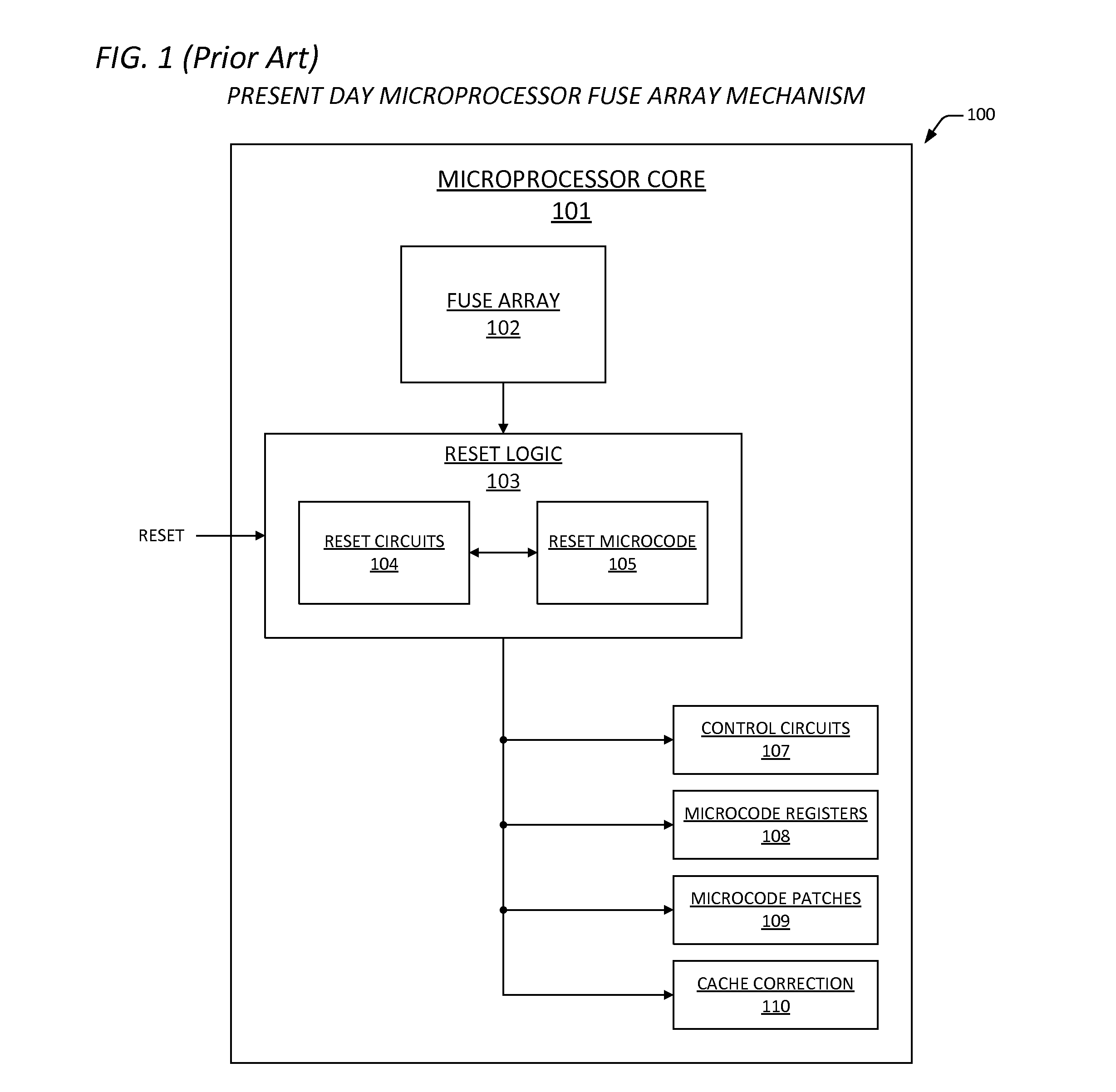
As device complexity has increased over the past years, the amount of configuration / repair data that is required for a typical device has proportionately increased.
This phenomenon, in and of itself, is a problem for designers, who are prevalently constrained by real estate and power considerations.
In other words, there is just not enough real estate on a given die to fabricate a huge fuse array.
In addition, the ability to fabricate multiple device cores on a single die has geometrically exacerbated the problem, because configuration requirements for each of the cores result in a requirement for a number of fuses on die, in a single array or distinct arrays, that is proportional to the number of cores disposed thereon.
Furthermore, as one skilled in the art will appreciate, multiple-core devices utilize complex power-saving modes of operation that result in one or more of the cores being powered down in a so-called power gating event (or, “sleep mode”) when not in use.

Method used


Image

  • Multi-core data array power gating restoral mechanism
  • Multi-core data array power gating restoral mechanism
  • Multi-core data array power gating restoral mechanism

Examples


Embodiment Construction

[0030]Exemplary and illustrative embodiments of the invention are described below. In the interest of clarity, not all features of an actual implementation are described in this specification, for those skilled in the art will appreciate that in the development of any such actual embodiment, numerous implementation specific decisions are made to achieve specific goals, such as compliance with system-related and business related constraints, which vary from one implementation to the next. In addition, it will be appreciated that such a development effort might be complex and time-consuming, but would nevertheless be a routine undertaking for those of ordinary skill in the art having the benefit of this disclosure. Various modifications to the preferred embodiment will be apparent to those skilled in the art, and the general principles defined herein may be applied to other embodiments. Therefore, the present invention is not intended to be limited to the particular embodiments shown ...


PUM


Abstract

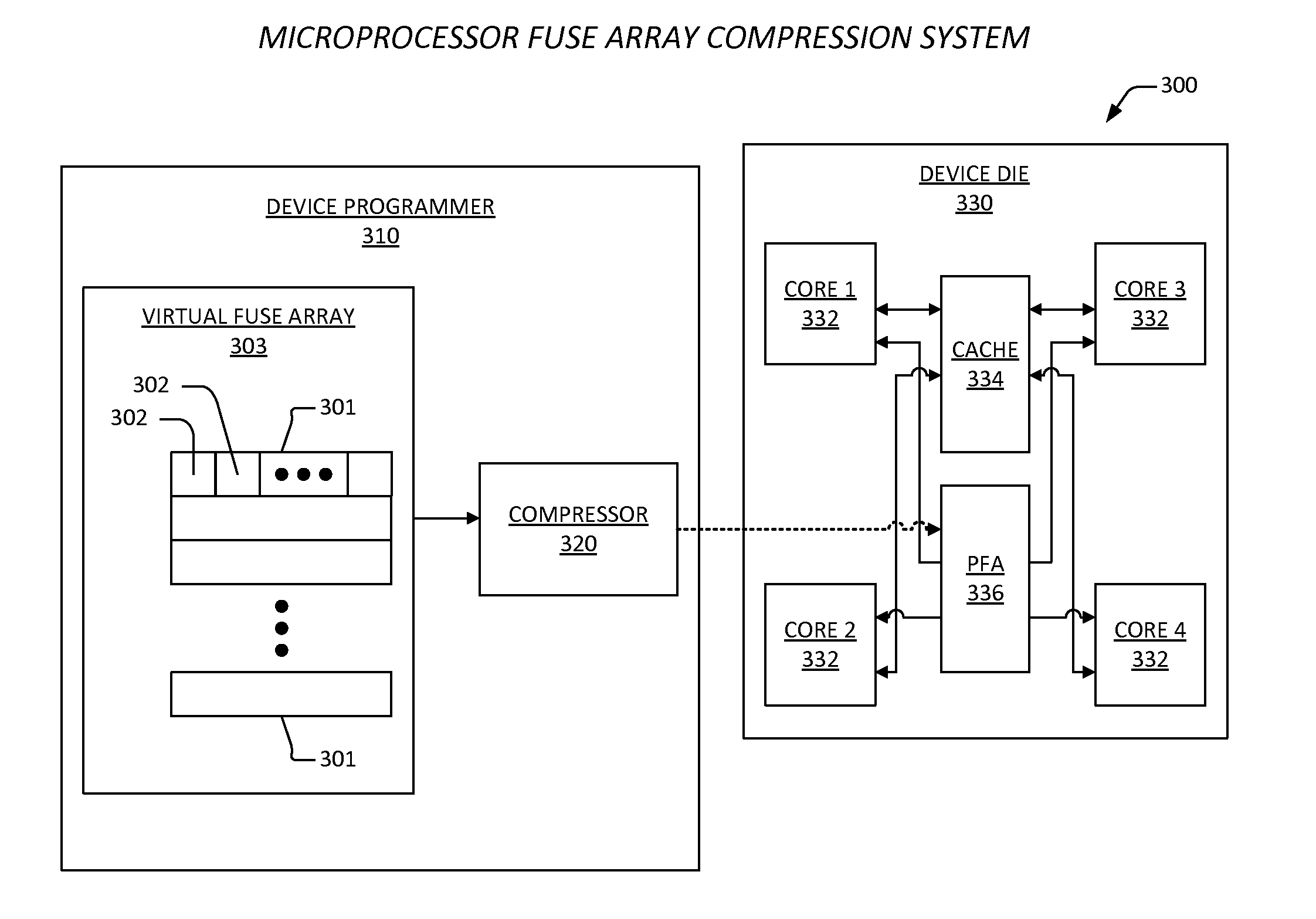
An apparatus includes a fuse array and a stores. The fuse array is programmed with compressed configuration data for a plurality of cores. The stores is coupled to the plurality of cores, and includes a plurality of sub-stores that each correspond to each of the plurality of cores, where one of the plurality of cores accesses the semiconductor fuse array upon power-up / reset to read and decompress the compressed configuration data, and to store a plurality of decompressed configuration data sets for one or more cache memories within the each of the plurality of cores in the plurality of sub-stores. Each of the plurality of cores has sleep logic. The sleep logic is configured to subsequently access a corresponding one of the each of the plurality of sub-stores to retrieve and employ the decompressed configuration data sets to initialize the one or more caches following a power gating event.

Description

CROSS-REFERENCE TO RELATED APPLICATIONS[0001]This application is related to the following co-pending U.S. patent applications, each of which has a common assignee and common inventors.SERIALFILINGNUMBERDATETITLE13972297Aug. 21, 2013APPARATUS AND METHOD FOR STORAGE AND(CNTR.2617)DECOMPRESSION OF CONFIGURATION DATA13972358Aug. 21, 2013MULTI-CORE FUSE DECOMPRESSION MECHANISM(CNTR.2672)13972414Aug. 21, 2013EXTENDED FUSE REPROGRAMMABILITY(CNTR.2673MECHANISM13972481Aug. 21, 2013APPARATUS AND METHOD FOR EXTENDED CACHE(CNTR.2674)CORRECTION13972657Aug. 21, 2013CORE-SPECIFIC FUSE MECHANISM FOR A MULTI-(CNTR.2675)CORE DIE13972609Aug. 21, 2013APPARATUS AND METHOD FOR CONFIGURABLE(CNTR.2686)REDUNDANT FUSE BANKS13972690Aug. 21, 2013APPARATUS AND METHOD FOR RAPID FUSE BANK(CNTR.2687)ACCESS IN A MULTI-CORE PROCESSOR13972725Aug. 21, 2013MULTI-CORE MICROPROCESSOR CONFIGURATION(CNTR.2697)DATA COMPRESSION AND DECOMPRESSIONSYSTEM13972741Aug. 21, 2013APPARATUS AND METHOD FOR(CNTR.2698)COMPRESSION OF CONF...

Claims


Application Information

Patent Timeline
Patent Type & Authority Applications(United States)
IPC IPC(8): G06F1/32G06F12/08G06F12/12
CPCG06F1/3275G06F12/12G06F2212/283G06F2212/69G06F12/0811G11C7/20G11C17/16G11C17/18G11C29/787G11C2029/4402G06F12/08G06F11/10G06F3/0604G06F3/0625G06F3/0631G06F3/064G06F3/0659G06F3/0679G06F12/0866G06F2212/1028G06F2212/1041G06F2212/214G06F2212/281G06F2212/313G06F2212/601G06F2212/608
Inventor HENRY, G. GLENNJAIN, DINESH K.GASKINS, STEPHAN
Owner VIA ALLIANCE SEMICON CO LTD
Learn More