Work vehicle and control method for same

a technology for working implements and control methods, applied in the field of work implements, can solve the problems of inability to determine the torque required for the work implement, affecting the load the work implement receives, and the engine output suited for driving the work implement and the driving travel device cannot be achieved

Active Publication Date: 2015-11-12
KOMATSU LTD
View PDF8 Cites 2 Cited by
  • Summary
  • Abstract
  • Description
  • Claims
  • Application Information

AI Technical Summary

Benefits of technology

[0012]The work implement required horsepower is determined on the basis of the operation amount of the work implement operating member and the hydraulic pressure of the hydraulic pump in the work vehicle according to the present exemplary embodiment. The hydraulic pressure of the hydraulic pump changes in response to a load on the work implement. As a result, the work implement required horsepower can be determined in response to the load on the work implement by taking into consideration the hydraulic pressure on the hydraulic pump when determining the work implement required horsepower. The engine required horsepower is then determined on the basis of the work implement required horsepower and the transmission required horsepower. As a result, an engine horsepower can be achieved that is suited to driving the work implement in response to the operation of the work implement by the operator and the load on the work implement, and suited to driving the travel device.
[0036]According to the present exemplary invention, an engine output suited to driving the work implement and driving the travel device can be achieved in a hybrid work vehicle.

Problems solved by technology

However, a torque required for the work implement is not determined merely from the operation of the work implement but also is affected by load that the work implement receives.
As a result, an engine output suited to driving the work implement and driving the travel device cannot be achieved.

Method used


Image

  • Work vehicle and control method for same
  • Work vehicle and control method for same
  • Work vehicle and control method for same

Examples


Embodiment Construction

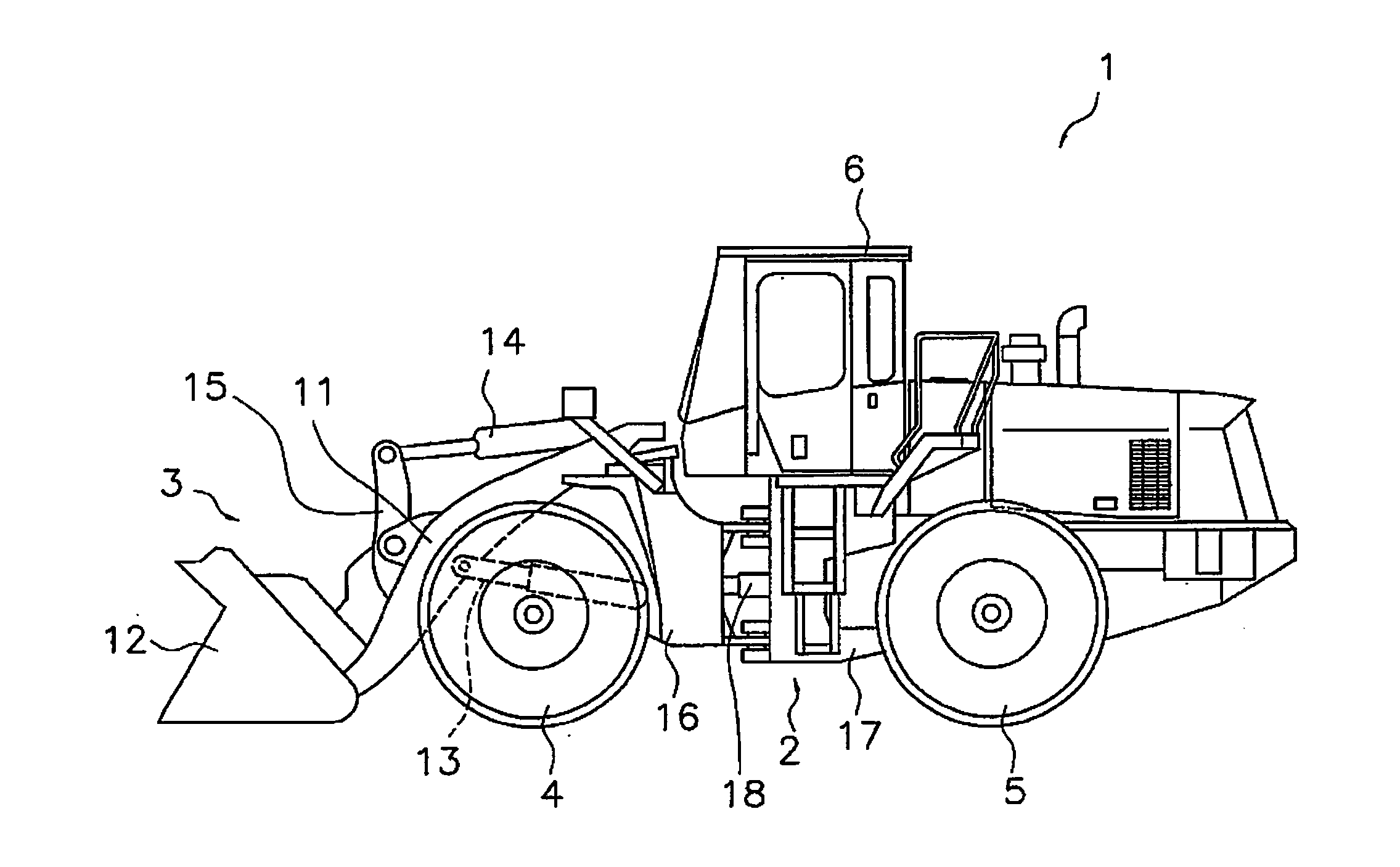
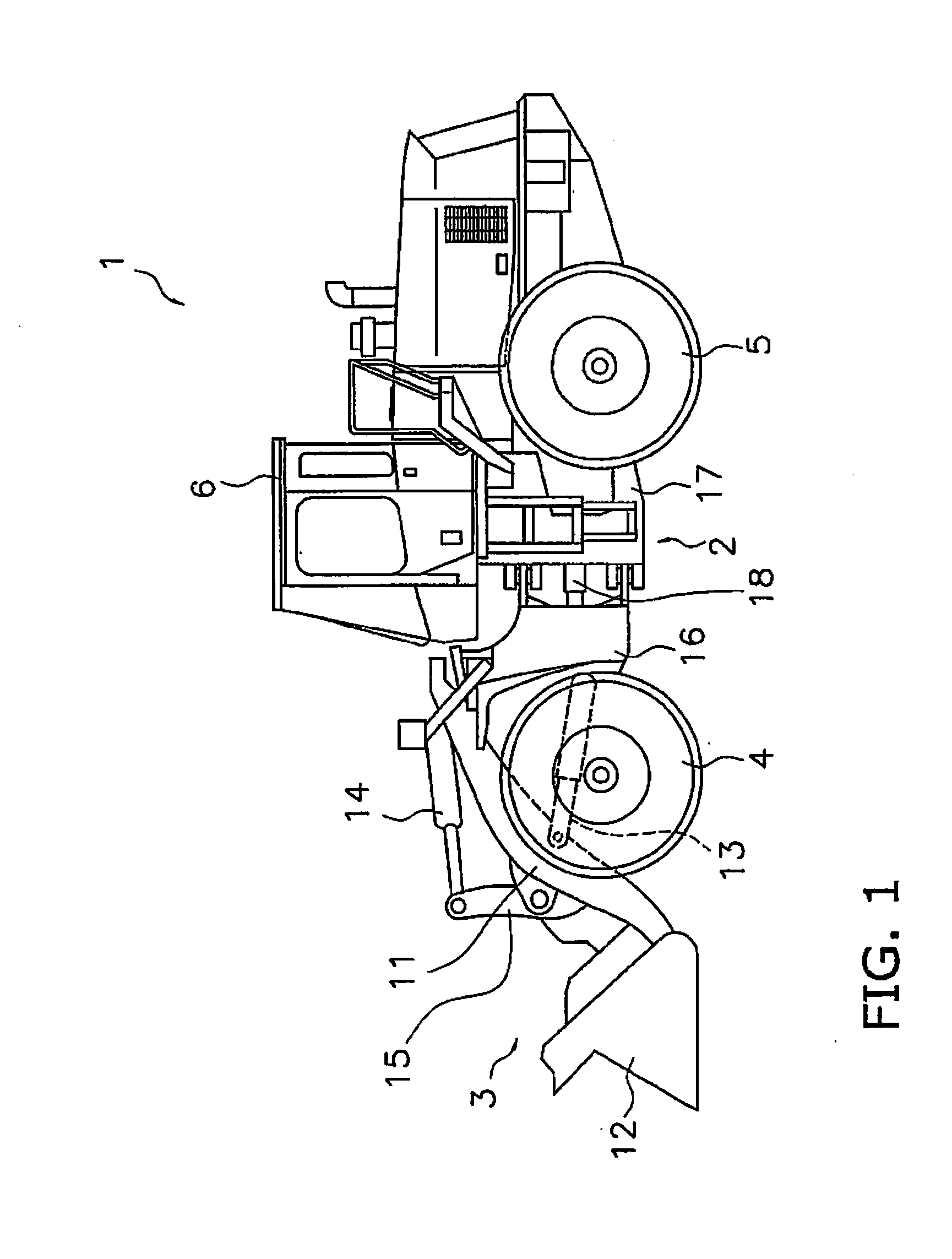
[0056]Exemplary embodiments of the present invention will be explained in detail with reference to the figures. FIG. 1 is a side view of a work vehicle 1 according to an exemplary embodiment of the present invention. As illustrated in FIG. 1, the work vehicle 1 is equipped with a vehicle body frame 2, a work implement 3, traveling wheels 4 and 5, and an operating cabin 6. The work vehicle 1 is a wheel loader and travels due to the traveling wheels 4 and 5 being rotated and driven. The work vehicle 1 is able to carry out work such as excavation by using the work implement 3.

[0057]The work implement 3 and the traveling wheels 4 are attached to the vehicle body frame 2. The work implement 3 is driven by hydraulic fluid from a below mentioned work implement pump 23 (see FIG. 2). The work implement 3 has a boom 11 and a bucket 12. The boom 11 is mounted on the vehicle body frame 2. The work implement 3 includes a lift cylinder 13 and a bucket cylinder 14. The lift cylinder 13 and the buc...


PUM


Abstract

The work implement requirement determination unit determines a work implement required horsepower on the basis of an operation amount of a work implement operating member and a hydraulic pressure of a hydraulic pump. A transmission requirement determination unit determines a transmission required horsepower on the basis of a vehicle speed and the operation amount of the accelerator operating member. An engine requirement determination unit determines an engine required horsepower on the basis of the work implement required horsepower and the transmission required horsepower. The required throttle determination unit determines a required throttle value based on an engine requirement.

Description

CROSS-REFERENCE TO RELATED APPLICATIONS[0001]This application is a U.S. National stage application of International Application No. PCT / JP2014 / 066883, filed on Jun. 25, 2014. This U.S. National stage application claims priority under 35 U.S.C. §119(a) to Japanese Patent Application No. 2013-136243, filed in Japan on Jun. 28, 2013, the entire contents of which are hereby incorporated herein by reference.BACKGROUND[0002]1. Field of the Invention[0003]The present invention relates to a work vehicle and a control method therefor.[0004]2. Background Information[0005]A power-transmission device (referred to hereinbelow as a “torque converter-type transmission”) having a torque converter and a multi-stage speed change gear is well known as a work vehicle such as a wheel loader. However, recently hydraulic mechanical transmissions (HMT) have become known as power-transmission devices in place of torque converter-type transmissions. As disclosed in Japanese Laid-Open Patent Publication No. 2...

Claims


Application Information

Patent Timeline
Patent Type & Authority Applications(United States)
IPC IPC(8): E02F3/28E02F3/42E02F9/02B60W20/00B60W10/06B60W10/08B60W10/115B60W10/26E02F9/20E02F9/22B60L50/16
CPCE02F3/283E02F9/2091E02F3/422E02F9/02E02F9/2075E02F9/2079Y10S903/93B60W10/06B60W10/08B60W10/115B60W10/26B60W20/00E02F9/2296B60K6/365B60K6/387B60K6/445B60K2006/381B60Y2200/411B60W2710/105B60W2710/0677Y10S903/945B60W50/0097B60W30/18127B60W30/1884B60W2300/17B60W2510/1005B60W2520/10B60W2540/10B60W2540/12B60W2710/0666B60W2710/083B60W20/11B60L15/2054B60L2200/40B60L2220/42B60L2240/423Y02T10/72B60L50/40B60L50/62B60L50/16Y02T10/62Y02T10/64Y02T10/70Y02T10/7072B60K6/485B60L15/20F16H3/66F16H2200/2007Y02T10/84
Inventor MIYAMOTO, SHUNSUKEMONDEN, HIROSHIHIRAKI, HIKOSABUROUFUJIWARA, YASUOOHKURA, YASUNORI
Owner KOMATSU LTD
Why Eureka
Try Eureka