
Amorphous inorganic anion exchanger, resin composition for electronic component sealing, and process for producing amorphous bismuth compound

Active Publication Date: 2015-11-12
TOAGOSEI CO LTD
View PDF0 Cites 11 Cited by
  • Summary
  • Abstract
  • Description
  • Claims
  • Application Information

AI Technical Summary

Benefits of technology

The present invention provides a production process for an amorphous bismuth compound that is in the form of microparticles and has high ion-exchange ability. This is conventionally not known. The invention also provides an inorganic anion exchanger with smaller particle size than conventional bismuth compounds and excellent performance in terms of ion exchange capacity and exchange rate. The technical effect is to provide a highly reliable resin composition for electronic component sealing using the inorganic anion exchanger.

Problems solved by technology

It is conventionally known that, although an epoxy resin is an excellent resin for sealing, it contains trace amounts of ionic impurities, and it is also known that there is a possibility that ionic impurities will corrode metal wiring of aluminum, etc. used in a wiring circuit for a semiconductor chip.
On the other hand, accompanying recent increases in integration and increases in the speed of semiconductor circuits, there has been a great increase in the temperature of semiconductor chips due to Joule heating generated when the circuit is operating; sealing materials comprise large amounts of flame retardants such as antimony oxide, brominated epoxy resins, inorganic hydroxides, etc., and because of these flame retardant components corrosion of metal wiring such as aluminum wiring occurs more readily.

Method used


Image

  • Amorphous inorganic anion exchanger, resin composition for electronic component sealing, and process for producing amorphous bismuth compound
  • Amorphous inorganic anion exchanger, resin composition for electronic component sealing, and process for producing amorphous bismuth compound
  • Amorphous inorganic anion exchanger, resin composition for electronic component sealing, and process for producing amorphous bismuth compound

Examples


example 1

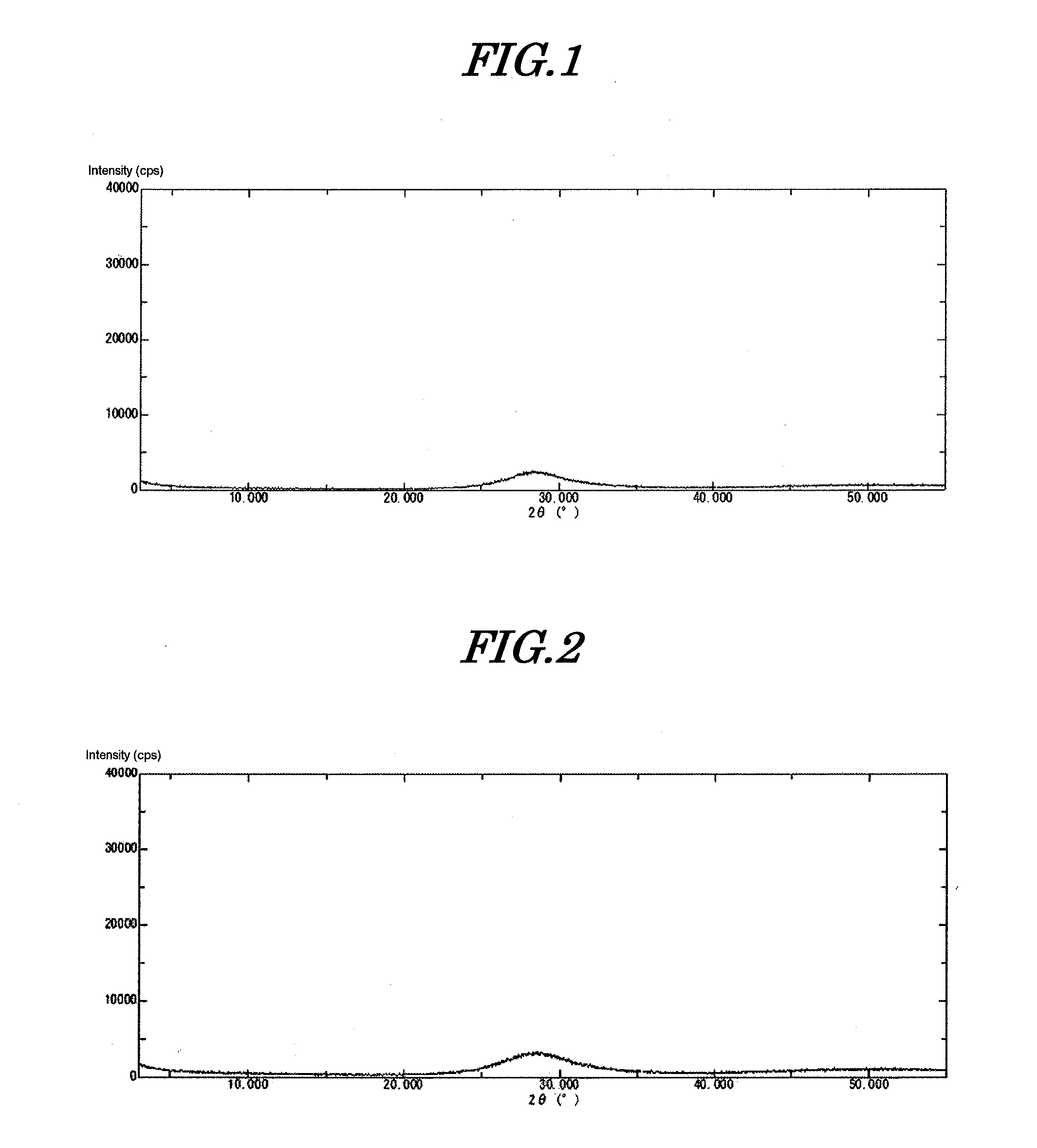
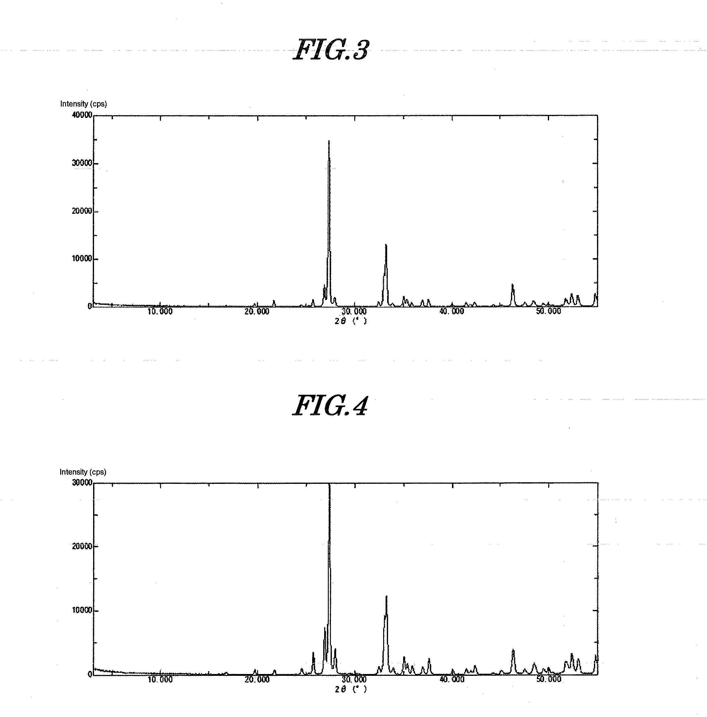
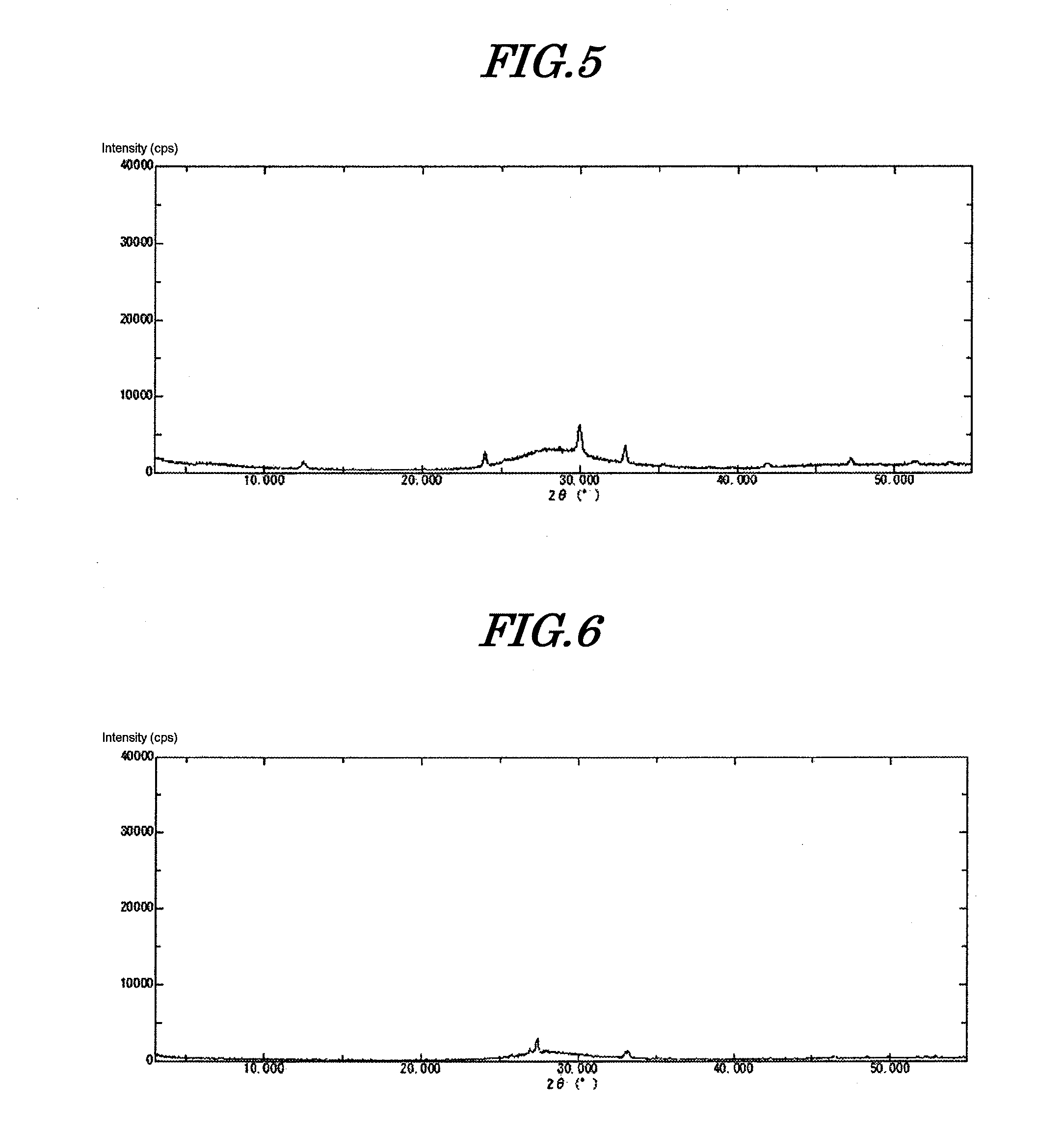
[0099]530 g of a 5% aqueous solution of sodium hydroxide was cooled to 5° C. Furthermore, 60 g of a 50% aqueous solution of bismuth nitrate was diluted with 200 g of 5% nitric acid, and cooled to 5° C.

[0100]The aqueous solution of sodium hydroxide prepared was placed in a 1 L beaker and stirred at 400 rpm while cooling at 5° C. (pH=14). The entire amount of the cooled bismuth aqueous solution was added thereto within 1 minute using a funnel. The pH of the slurry after the dropwise addition was 13.0.

[0101]The precipitate thus obtained was immediately filtered, and the precipitate was washed with deionized water at 10° C. until the conductivity of the filtrate became no greater than 50 μS / cm. Filtration and washing were completed in 30 minutes. This precipitate was dried at 120° C. for 24 hours. Subsequently it was ground using a Fritsch Rotor-Speed Mill to give amorphous inorganic anion exchanger (amorphous bismuth compound) 1. This compound was subjected to ICP analysis, thus determ...

example 2

[0108]530 g of a 10% aqueous solution of sodium hydroxide was cooled to 5° C. Furthermore, 180 g of a 50% aqueous solution of bismuth nitrate was diluted with 420 g of 5% nitric acid. 2.8 g of tartaric acid was added thereto, dissolved, and cooled to 5° C. The aqueous solution of sodium hydroxide prepared was placed in a 2 L beaker and stirred at 400 rpm while cooling at 5° C. (pH=14). The entire amount of the cooled bismuth aqueous solution was added thereto within 1 minute using a funnel. The pH of the slurry after the dropwise addition was 13.2. The precipitate thus obtained was immediately filtered and washed with deionized water at 10° C. until the conductivity of the filtrate became no greater than 50 μS / cm. Filtration and washing were completed in 30 minutes. This precipitate was dried at 120° C. for 24 hours. Subsequently, it was ground to give amorphous inorganic anion exchanger (amorphous bismuth compound) 2. When this compound was analyzed, it was found to be BiO(OH), and...

example 3

[0110]530 g of a 10% aqueous solution of sodium hydroxide was cooled to 10° C. Furthermore, 180 g of a 50% aqueous solution of bismuth nitrate was diluted with 420 g of 5% nitric acid. 2.8 g of tartaric acid was added thereto, dissolved, and cooled to 10° C. The aqueous solution of sodium hydroxide prepared was placed in a 2 L beaker and it was stirred at 400 rpm while cooling at 10° C. (pH=14). The entire amount of the cooled bismuth aqueous solution was added thereto within 1 minute using a funnel. The pH of the slurry after the dropwise addition was 13.2. The precipitate thus obtained was immediately filtered and washed with deionized water at 10° C. until the conductivity of the filtrate became no greater than 50 μS / cm. Filtration and washing were completed in 30 minutes. This precipitate was dried at 120° C. for 24 hours. Subsequently, it was ground to give amorphous inorganic anion exchanger (amorphous bismuth compound) 3. When this compound was analyzed, it was found to be Bi...


PUM

PropertyMeasurementUnit
Temperatureaaaaaaaaaa

Abstract

The object is to provide an amorphous inorganic anion exchanger having excellent anion exchangeability and suppressed corrosivity toward metals and to provide a production process that can produce an amorphous bismuth compound having excellent anion exchangeability and suppressed corrosivity toward metals.The amorphous inorganic anion exchanger of the present invention is represented by Formula (1) and has an average primary particle size observed with an electron microscope of at least 1 nm but no greater than 500 nm and an NO3 content of no greater than 1 wt % of the whole.The process for producing an amorphous bismuth compound of the present invention includes a precipitate formation step of forming a precipitate by subjecting an acidic aqueous solution containing trivalent Bi ions to a temperature in the range of higher than 0° C. but less than 20° C. and a pH of at least 12, the amorphous bismuth compound thus obtained being represented by Formula (1) and having an NO3 content of no greater than 1 wt %.BiO(OH)  (1)

Description

TECHNICAL FIELD[0001]The present invention relates to an amorphous inorganic anion exchanger, a resin composition for electronic component sealing, resin for electronic component sealing, electronic component, varnish, adhesive, paste, and article comprising the amorphous inorganic anion exchanger, and a process for producing an amorphous bismuth compound.BACKGROUND ART[0002]Many electronic components such as LSIs, ICs, hybrid ICs, transistors, diodes, thyristors, and hybrid components thereof are usually sealed using a resin composition for electronic component sealing in order to protect an electronic circuit or package from the influence of contamination, moisture, etc. from the external environment. Such an electronic component sealing material is required to suppress failure due to ionic impurities in starting materials or moisture entering from the outside as well as to have various properties such as flame retardancy, high adhesion, anti-cracking properties, and electrical pr...

Claims


Application Information

Patent Timeline
IPC IPC(8): B01J41/02C08K3/22B32B7/12C01G29/00B01J41/10
CPCB01J41/02C01G29/00B01J41/10B32B7/12Y10T428/2982B32B2264/102B32B2457/00Y10T428/239Y10T428/25C08K3/22B01J39/09B01J39/12B01J39/14B01J41/14B01J47/04C01P2002/02C01P2002/72C01P2004/61C01P2006/12C01P2006/80C09J11/04H01L23/293H01L2924/0002H01L2924/00C08L101/00C09J201/00
Inventor MIYAMURA, KENTAROUIINUMA, TOMOHISAONO, YASUHARU
Owner TOAGOSEI CO LTD
Learn More