
Apparatus and method for adjusting beam pattern in communication system supporting beam division multipile access scheme

a communication system and beam pattern technology, applied in the field of apparatus and method for adjusting the beam pattern in the communication system supporting the beam division multiple access (bdma) scheme, can solve the problems of automatic impedance matching scheme not working, difficult to guarantee performance, and degradation of communication performance of portable terminals, so as to reduce the effect of external factors, increase communication system performance, and reduce the degradation of beam pattern gain

Active Publication Date: 2015-11-05
SAMSUNG ELECTRONICS CO LTD +1
View PDF2 Cites 216 Cited by
  • Summary
  • Abstract
  • Description
  • Claims
  • Application Information

AI Technical Summary

Benefits of technology

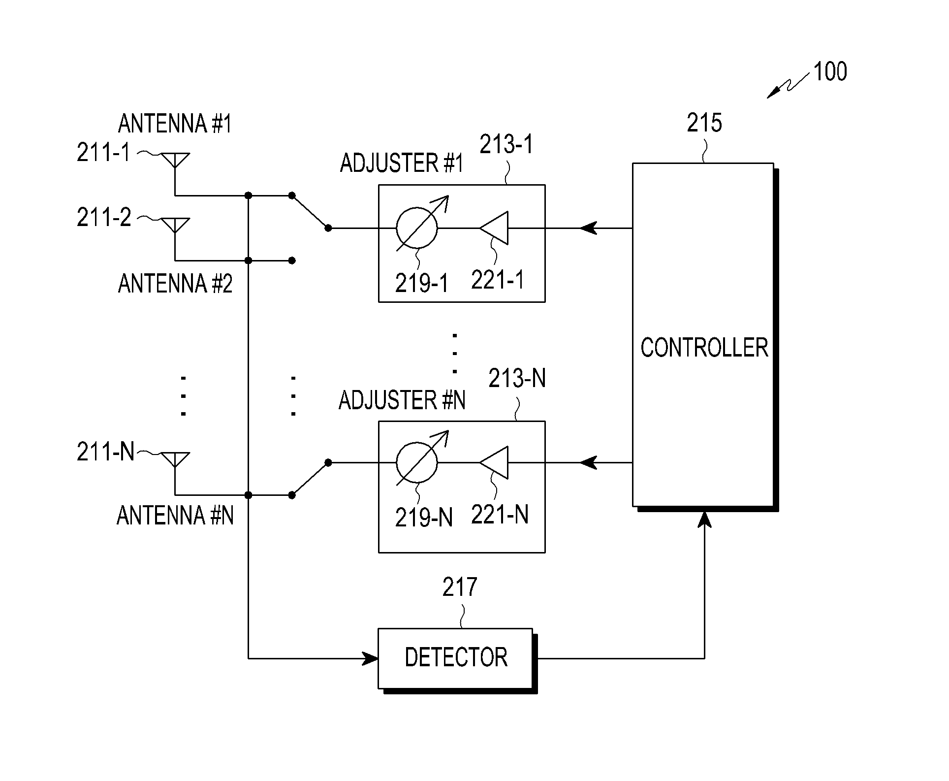
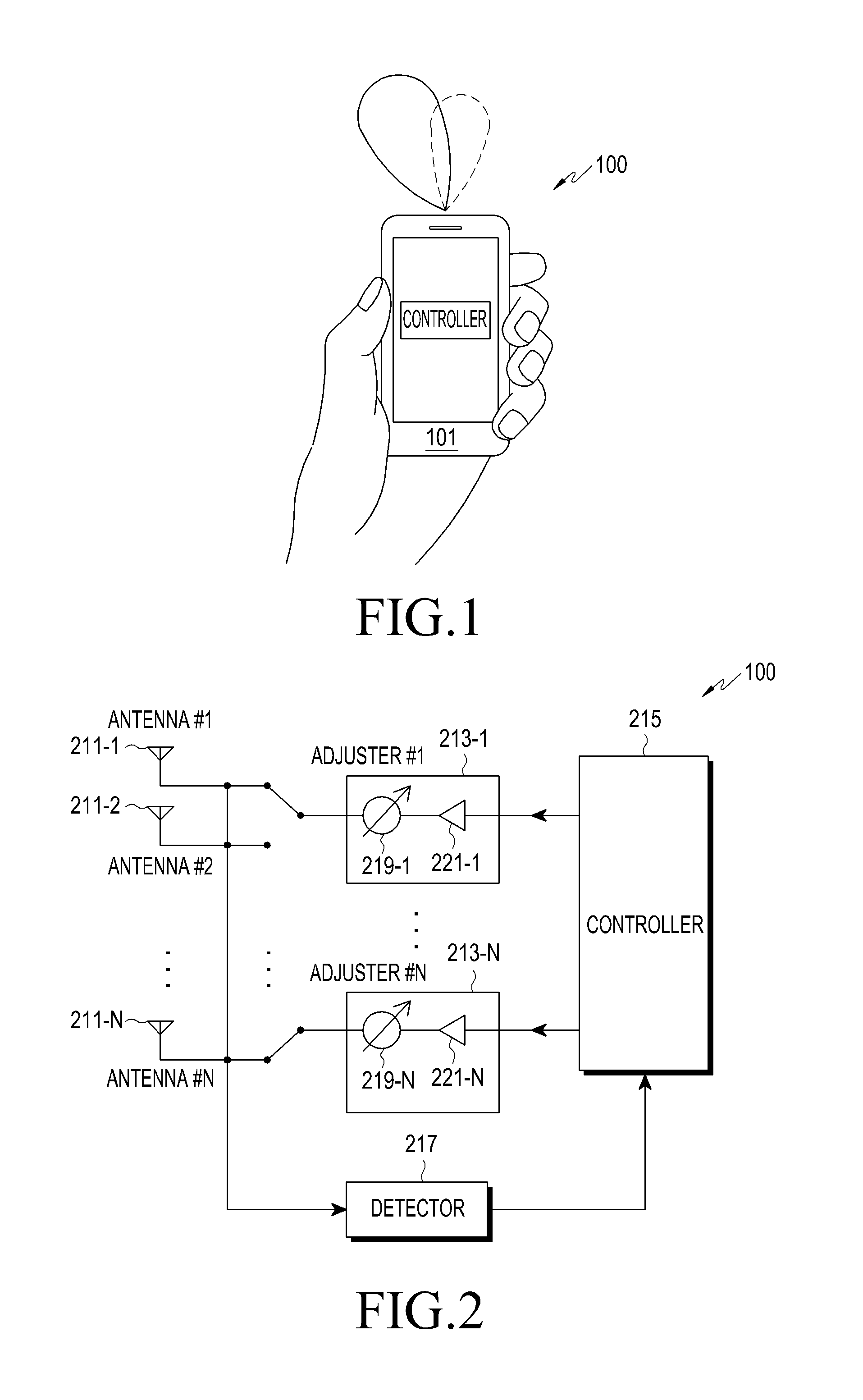
The present invention provides a method for adjusting the beam pattern of an array of antennas to decrease degradation of beam pattern gain, and increase the performance of communication systems supporting a BDMA scheme. It also decreases the impact of external factors on the array of antennas, leading to improved communication performance. Furthermore, the invention increases the channel capacity in such communication systems.

Problems solved by technology

Due to this change of the antenna characteristic, an impedance matching between an antenna side and a system side is not performed for the antenna used in the portable terminal, that is, an impedance mismatch occurs in the antenna used in the portable terminal, which can lead to degradation of communication performance of the portable terminal.
However, in a relatively high frequency band, e.g., a frequency band which is greater than or equal to 10 GHz, it is difficult to guarantee performance thereof even though the automatic impedance matching scheme is used.
However, since the automatic impedance matching scheme targets impedance matching for an individual antenna not impedance matching for a plurality of antenna elements, the automatic impedance matching scheme does not consider various situations that may occur in an array of antennas, e.g., distortion of a beam, and the like.

Method used


Image

  • Apparatus and method for adjusting beam pattern in communication system supporting beam division multipile access scheme
  • Apparatus and method for adjusting beam pattern in communication system supporting beam division multipile access scheme
  • Apparatus and method for adjusting beam pattern in communication system supporting beam division multipile access scheme

Examples


Embodiment Construction

[0037]Hereinafter, embodiments of the present invention are described in detail with reference to the accompanying drawings. Those of ordinary skill in the art will recognize that various changes and modifications of the embodiments described herein can be made without departing from the scope and spirit of the present invention. In addition, descriptions of well-known functions and constructions may be omitted for clarity and conciseness. The same reference symbols are used throughout the drawings to refer to the same or like parts.

[0038]It should be noted that various embodiments described below may be applied or used individually or in combination.

[0039]The terms and words used in the following description and claims are not limited to their dictionary meanings, but, are merely used to enable a clear and consistent understanding of the present invention. Accordingly, it should be apparent to those skilled in the art that the following description of various embodiments of the pre...


PUM


Abstract

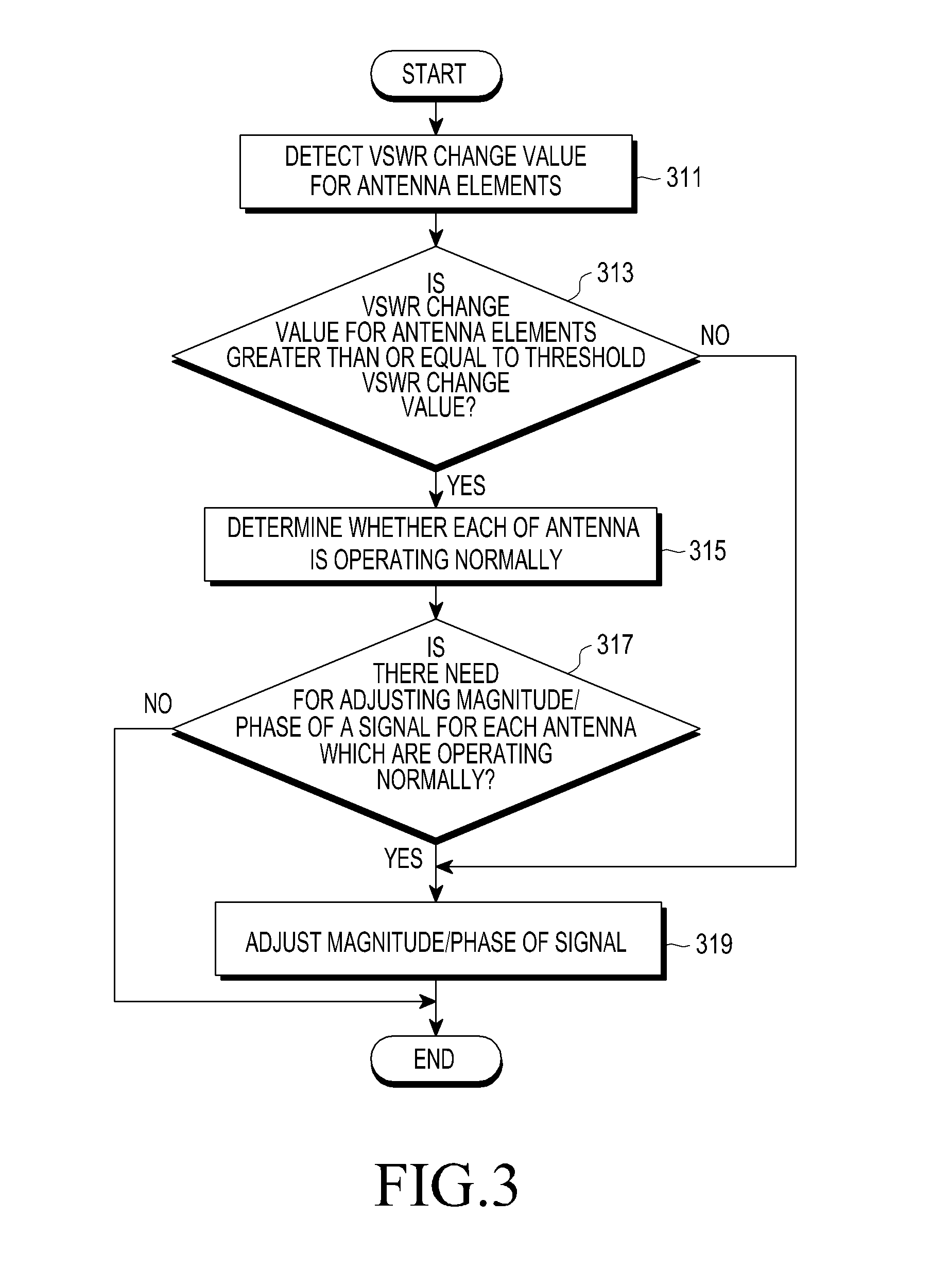
A method for adjusting a beam pattern in a beam pattern adjusting apparatus in a communication system supporting a Beam Division Multiple Access (BDMA) scheme is provided. The method includes determining whether a Voltage Standing Wave Ratio (VSWR) value for each antenna included in an antenna array included in the beam pattern adjusting apparatus is greater than or equal to a threshold VSWR value, if it is determined that an antenna of the antenna array has a VSWR value that is greater than or equal to the threshold VSWR, detecting whether each of the antenna elements is operable, and if it is determined that at least one of the antennas is inoperable, adjusting a beam pattern of at least one of the antennas that is operable.

Description

PRIORITY[0001]This application claims priority under 35 U.S.C. §119(a) to Korean Patent Application Serial No. 10-2014-0052744, which was filed in the Korean Intellectual Property Office on Apr. 30, 2014, the entire disclosure of which is incorporated herein by reference.BACKGROUND OF THE INVENTION[0002]1. Field of the Invention[0003]The present invention relates generally to an apparatus and method for adjusting a beam pattern in a communication system supporting a Beam Division Multiple Access (BDMA) scheme, and more particularly, to an apparatus and method for adjusting a beam pattern for an array antenna including at least two antenna elements in a communication system supporting a BDMA scheme.[0004]2. Description of the Related Art[0005]Generally, when a user holds a portable terminal in their hand, a characteristic of an antenna used in the portable terminal can change due to an electromagnetic characteristic which is associated with the user's body, such as the hand, head, or...

Claims


Application Information

Patent Timeline
Patent Type & Authority Applications(United States)
IPC IPC(8): H01Q3/24H04B7/04H04L25/02H01Q3/34H01Q3/28
CPCH01Q3/24H01Q3/34H04B7/0408H04L25/0278H01Q3/28H01Q1/1257H01Q1/242H01Q3/26H01Q21/06H04B7/0617H04B17/12H04L25/02H04B7/0404
Inventor LEE, WON-SEOKKIM, YONG-HOONOH, KYOUNG-SUBYU, JONG-WONYOO, SOL-JI
Owner SAMSUNG ELECTRONICS CO LTD
Learn More