Microwave plasma applicator with improved power uniformity

Active Publication Date: 2015-11-05
MKS INSTR INC
View PDF7 Cites 18 Cited by
  • Summary
  • Abstract
  • Description
  • Claims
  • Application Information

AI Technical Summary

Benefits of technology

The patent describes a device that generates plasma using a conductive coil. The device is designed to have a specific angle between the electric field and the plasma discharge tube to increase the uniformity of power absorption. The spacing between the loops of the conductive coil can also be adjusted to control the electric current and improve the efficiency of power absorption. The device has technical effects in improving plasma generation and efficiency.

Problems solved by technology

One technical difficulty in using microwave energy for creating a large quantity of reactive gaseous species in a plasma source is cooling the plasma discharge tube or dielectric window.
Air cooling can be used for the plasma discharge tube, but it is relatively inefficient compared with liquid cooling.
In addition, air cooling requires relatively large and expensive air blowers or compressors to remove a sufficient amount of heat.
Also, air cooling may not be compatible with modern clean room environments used for manufacturing semiconductors.
A barrier to using water for cooling microwave plasma discharge tubes is that water also readily absorbs microwave energy.
Unfortunately, these fluids are often environmentally undesirable, hazardous to handle, and expensive.
In addition, using these fluids requires the use of closed-loop heat exchangers, which further increases the cost and complexity of the system.
None of the prior devices have been adequate for producing high-flow-rate, contamination-free, chemically activated gases useful for industrial applications.

Method used


Image

  • Microwave plasma applicator with improved power uniformity
  • Microwave plasma applicator with improved power uniformity
  • Microwave plasma applicator with improved power uniformity

Examples


Embodiment Construction

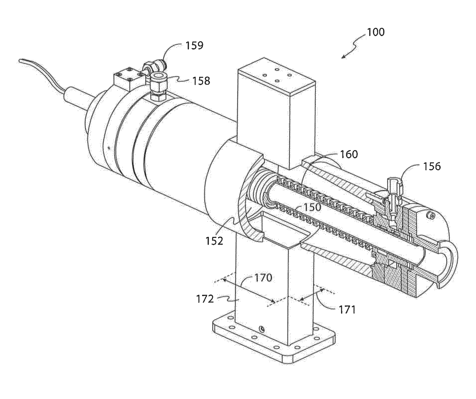
[0044]U.S. Pat. No. 5,625,259 (hereinafter, “the '259 patent”), incorporated herein in its entirety by reference, discloses that a microwave electric field oriented in a particular direction can be efficiently coupled to a microwave plasma discharge tube having a channel containing a microwave absorbing cooling liquid surrounding the plasma discharge tube in a certain path. For example, a microwave electric field oriented parallel to a longitudinal axis extending through the center of the plasma discharge tube will efficiently couple to the plasma discharge tube having a cooling channel encircling the tube in a helical path.

[0045]Furthermore, a microwave electric field oriented in a particular direction can be efficiently coupled to a dielectric window having one or more channels in contact with the window and containing a microwave absorbing cooling liquid. For example, a microwave electric field oriented parallel to the surface of the window will efficiently couple to a plasma dis...


PUM


Abstract

An apparatus for generating plasma includes a plasma discharge tube and a conductive coil helically wound around an outer surface of the plasma discharge tube. A waveguide is coupled to a microwave cavity surrounding the plasma discharge tube to guide the microwave energy into the plasma discharge tube such that the plasma is generated in the plasma discharge tube. The waveguide is positioned such that an electric field of the microwave energy is oriented at a predetermined angle with respect to the longitudinal axis of the plasma discharge tube. A resulting induced electric current in the conductive coil affects power absorption in the plasma discharge tube, the predetermined angle being selectable such that power absorption in the plasma discharge tube is according to a predetermined profile with respect to the longitudinal axis of the plasma discharge tube.

Description

RELATED APPLICATION[0001]This application is a continuation-in-part (CIP) of copending U.S. patent application Ser. No. 14 / 226,994, filed in the U.S. Patent and Trademark Office on Mar. 27, 2014, the entire contents of which are incorporated herein by reference.BACKGROUND[0002]1. Technical Field[0003]This disclosure is related to microwave plasma systems and, more particularly, to a fluid-cooled microwave plasma applicator for producing reactive gaseous species for processing applications.[0004]2. Discussion of Related Art[0005]Reactive gases and gas mixtures are used in many industrial operations including the processing of materials such as semiconductor wafers for fabricating electronic and optical devices. Reactive gases can be used, for example, in thin film deposition and etching in microelectronics manufacturing to etch dielectric and semiconductor materials or various masking films such as photoresist and polyimide. Reactive gasses can be used to form dielectric films and me...

Claims


Application Information

Patent Timeline
IPC IPC(8): H01J37/32
CPCH01J37/32229H01J37/32201H01J37/32311H01J37/32522H05H1/46H05H1/4622
Inventor CHEN, XINGJI, CHENGXIANGMADDEN, ERINPOKIDOV, IIYAWENZEL, KEVIN W.
Owner MKS INSTR INC
Why Eureka
Try Eureka