Transmitting/receiving antenna, isolator, high-frequency oscillator, and high-frequency transmitter-receiver using the same

Inactive Publication Date: 2005-09-01
KYOCERA CORP
View PDF37 Cites 272 Cited by
  • Summary
  • Abstract
  • Description
  • Claims
  • Application Information

AI Technical Summary

Benefits of technology

[0060] Another object of the invention is to provide a transmitting / receiving antenna, which can prevent a portion of the mill-wave signal of the transmission system from leaking directly into the reception system, and a millimeter-wave transmitter-receiver using the transmitting / receiving antenna to have a high millimeter-wave transmitting / receiving performance.
[0203] According to the invention, the radar-apparatus mounted small-sized boat includes the radar apparatus of the invention, in which the radar apparatus is used for detecting the objective. Therefore, the radar apparatus can detect the objective such as another vehicle or the obstacle on the road rapidly and reliably so that the apparatus can allow a proper control of the vehicle and can give a proper warning to the driver without causing an abrupt behavior in the vehicle for avoiding another vehicle or the obstacle.

Problems solved by technology

In the pulse modulation system, however, a portion of the pulse-modulated transmission millimeter-wave signal is outputted as an unnecessary signal to the reception system by the reflection or the like in the transmitter-receiver.
This output raises a problem that the reception performance is adversely affected.
In the configuration proposed by Japanese Unexamined Patent Publication JP-A 2003-198421, however, we have made keen investigations for enhancing the performance of the millimeter-wave transmitter-receiver more and have found the following problems desired to be improved.
Even if an ideal pulse signal is inputted for the driving purpose, the modulating bias current is accompanied in most cases by the transient fluctuation such as the ringing noise.
As a result, the mill-wave signal output from the pulse modulator 412 is distorted from its original waveform thereby to raise a problem that the signal output is accompanied by the level fluctuation distorted from the design concept.
Before the aforementioned level fluctuation is converged and stabilized to a steady state, therefore, the switch 416 cannot be turned ON thereby to raise a problem that the transmission / reception cannot be performed for a constant time period just after the pulse signal was sent out.
For this effective method, the configuration is complicated to raise problems that the increase in the number of steps of assembling the millimeter-wave transmitter-receiver and the enlargement of the sizes of the millimeter-wave transmitter-receiver itself and the millimeter-wave radar apparatus using the millimeter-wave transmitter-receiver are invited.
Moreover, the transmitting / receiving antenna of the related art, as disclosed in Japanese Unexamined Patent Publication JP-A 2000-258525 or Japanese Unexamined Patent Publication JP-A 6-188633, has a problem that the portion of the mill-wave signal inputted from the transmission system leaks from the first dielectric guide 424 to the second dielectric guide 425 and is mixed with the millimeter-wave signal to be received, thereby to deteriorate the reception characteristics of the reception system.
This synthesization raises a problem that it is impossible to sufficiently attenuate the high-frequency signal which might otherwise be reflected on the output terminal of the second transmission line 435 to leak to the input terminal of the first transmission line 434.
This raises a problem that the oscillatory frequency band is limited (e.g., 1 GHZ or less in the example of FIG. 16) is restricted fro the stable oscillation of the high-frequency oscillator within the range where the isolation can be at a predetermined or higher value of 30 dB or more.
This dependency raises a problem that the high-frequency oscillator outputs millimeter-wave oscillations with such a frequency thereby to deteriorate the radar detecting performance that the isolation of the circulator cannot be made at the environmental temperature.
In this case, the pulsating mill-wave signal returns from the pulse modulator to the high-frequency oscillator of the related art so that a more serious factor for the oscillation instability is added to the voltage-controlled oscillator.
This addition raises a problem that the isolation of the circulator becomes short.
As a result, the ON / OFF ratio or the ratio of the intensities of the individual transmission high-frequency signals, which are transmitted from the transmitting / receiving antenna 65 when the pulse modulator 63 are ON and OFF, drops to raise a problem that the transmission / reception performance drops.
Specifically, this unnecessary high-frequency signal migrates, if transmitted, into the high-frequency signal RF to be intrinsically received, thereby to raise a problem that the portion of the high-frequency signal RF to be received cannot be correctly received.
As a result, the range to be detected may be narrowed, or an erroneous detection may occur thereby to cause a problem that the detection of the objective is delayed.
However, the detection of the objective is delayed to raise a problem that the delayed detection may cause an abrupt behavior in the vehicle or the small-sized boat.

Method used


Image

  • Transmitting/receiving antenna, isolator, high-frequency oscillator, and high-frequency transmitter-receiver using the same
  • Transmitting/receiving antenna, isolator, high-frequency oscillator, and high-frequency transmitter-receiver using the same
  • Transmitting/receiving antenna, isolator, high-frequency oscillator, and high-frequency transmitter-receiver using the same

Examples


examples

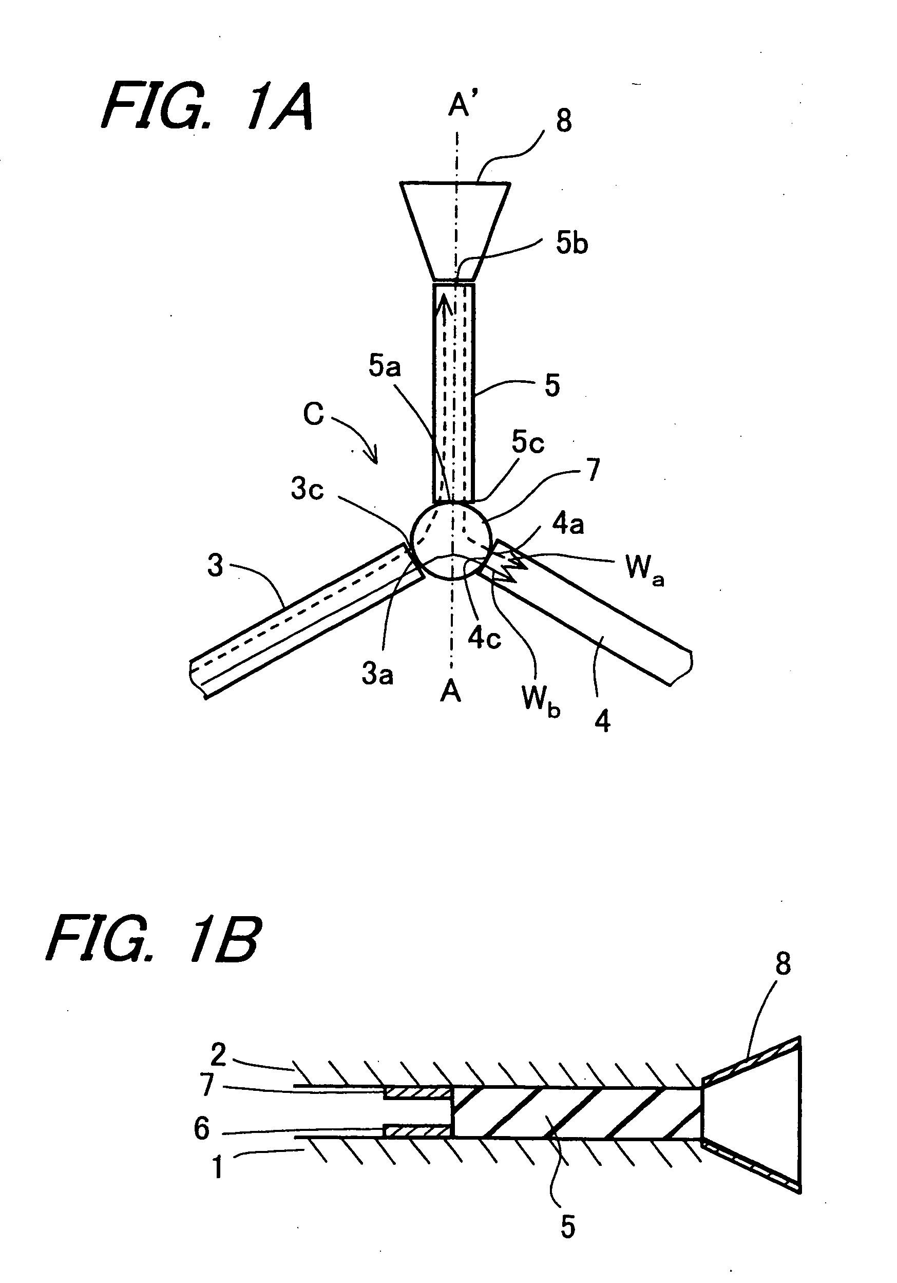
[0411] The mill-wave oscillator O shown in FIG. 13 was configured in the following manner. At first, two Al plates having a thickness of 6 mm were arranged as the parallel flat plate conductors 20 at a spacing of a=1.8 mm. Between these plates, there were so arranged the two ferrite plates 121a and 121b having a diameter of 2 mm and the later-described thickness of t mm that the ferrite plates were brought into close contact with the upper flat plate conductor and the lower flat plate conductor, respectively, and confronted each other while having their center axes lying on the common straight line. Around the ferrite plates 121a and 121b, moreover, there were radially arranged the inputting dielectric guide 122, the terminating dielectric guide 124 and the inputting / outputting dielectric guide 125, which were made of cordierite ceramics having a sectional shape of a rectangle of 1.8 mm (height)×0.8 mm (width) and a specific dielectric constant of 4.8, thereby to configure the first...

example

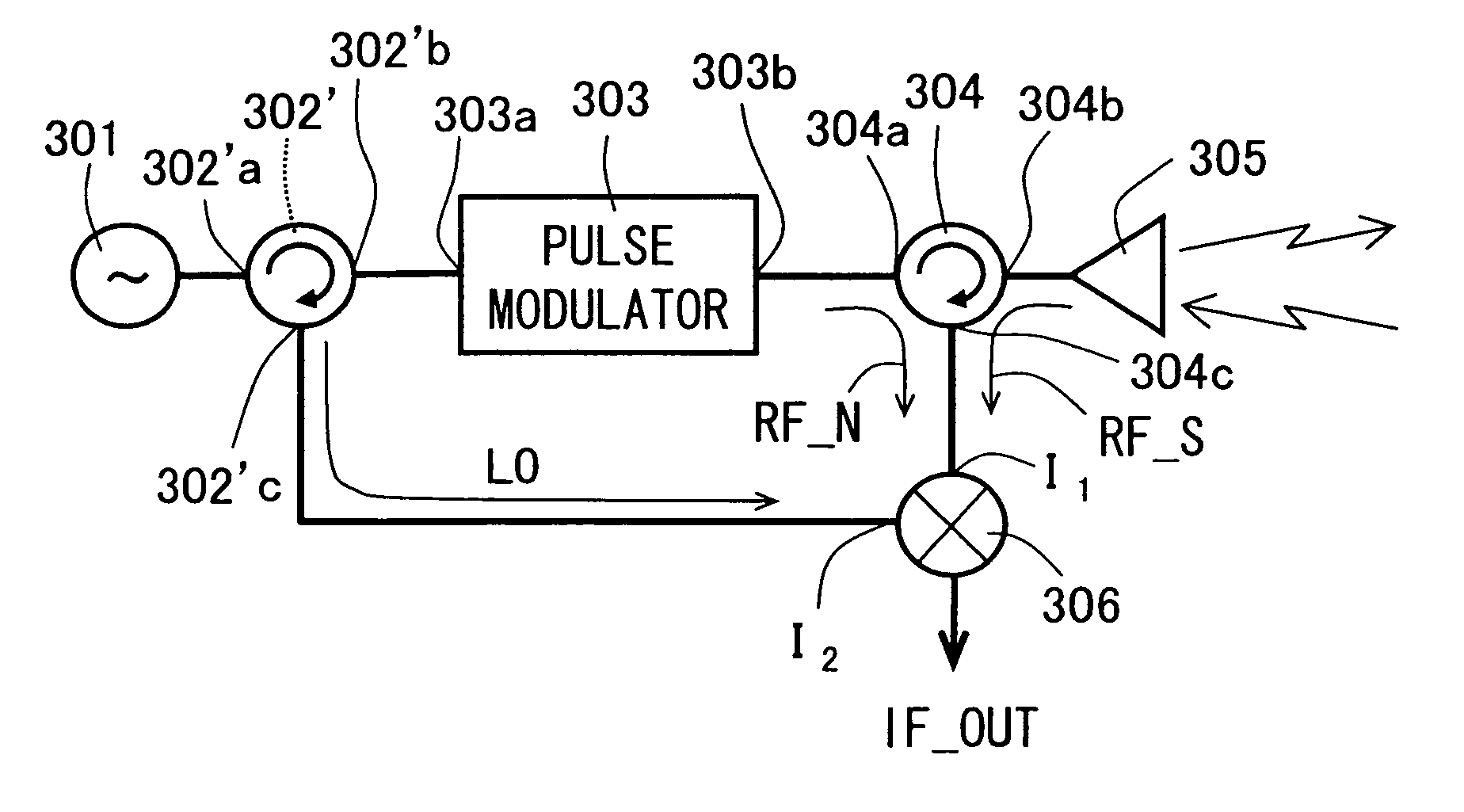
[0506] The high-frequency transmitter-receiver of the thirteenth embodiment of the invention, as shown in FIG. 21, was configured in the following manners. Two Al plates having a thickness of 6 mm were arranged as the parallel flat plate conductors 1 (2) at a spacing of 1.8 mm. Between the two Al plates, there were arranged the first to fifth dielectric guides 316 to 320, which were made of cordierite ceramics having a rectangular sectional shape of 1.8 mm (height)×0.8 mm (width) and a specific dielectric constant of 4.8. At this time, the circulator 304 was configured by arranging one of the two ferrite plates 315 having a diameter of 2 mm and a thickness of 0.23 mm in close contact with the upper side parallel flat plate conductor and the other in close contact with the lower side parallel flat plate conductor so that the ferrite plates confronted each other while having their center axes on the common straight line, and by arranging the second dielectric guide 317, the third diel...


PUM


Abstract

A millimeter-wave transmitter-receiver uses an NRD guide as a fundamental configuration and includes a millimeter-wave signal oscillator, a pulse modulator, a circulator, an antenna and a mixer. In the millimeter-wave transmitter-receiver, a line length of a third dielectric guide is set so that δ=±π in which δ is a phase difference at a center frequency between a portion of a transmission millimeter-wave signal, which is reflected via a third dielectric guide on the leading end portion of the third dielectric guide and returned to leak to a third connecting portion of the circulator, and another portion of the millimeter-wave signal, which leaks from a first connecting portion to the third connecting portion of the circulator. It is possible to reduce the change in the mixer output and enhance the millimeter-wave transmission / reception performance.

Description

BACKGROUND OF THE INVENTION [0001] 1. Field of the Invention [0002] The present invention relates to a millimeter-wave transmitter-receiver using a non-radiative dielectric waveguide (i.e., NRD guide) employed in a millimeter-wave radar module, a millimeter-wave wireless telegram or the like and, more particularly, to a suppression of fluctuations of an output signal coming from a mixer due to the transient characteristics of a pulse modulator while such a switching controller of the millimeter-wave transmitter-receiver being closed (ON) as can shield the pulse-modulated transmission millimeter wave signal, which might otherwise be outputted to a reception system by an internal reflection or the like. The invention further relates to a transmitting / receiving antenna, in which an antenna (including a primary radiator) is connected to one of inputting / outputting transmission lines of a circulator, for preventing a portion of a millimeter-wave signal of a transmission system from leaki...

Claims


Application Information

Patent Timeline
IPC IPC(8): G01S7/03H01P1/38H01Q13/24
CPCG01S7/03H01Q13/24H01P1/38
Inventor HIRAMATSU, NOBUKIKISHIDA, YUJIHAYATA, KAZUKIOYA, YOSHIKOTAKENOSHITA, TAKESHI
Owner KYOCERA CORP
Why Eureka
Try Eureka